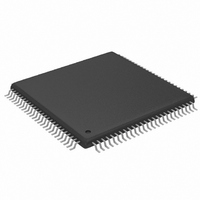
MAX2038CCQ+ Maxim Integrated Products, MAX2038CCQ+ Datasheet - Page 21

MAX2038CCQ+
Manufacturer Part Number
MAX2038CCQ+
Description
IC VGA W/OCTAL MIXER 8CH 100TQFP
Manufacturer
Maxim Integrated Products
Type
Variable Gain Amplifierr
Datasheet
1.MAX2038CCQT.pdf
(24 pages)
Specifications of MAX2038CCQ+
Applications
Medical Ultrasound Imaging, Sonar
Mounting Type
Surface Mount
Package / Case
100-TQFP Exposed Pad, 100-eTQFP, 100-HTQFP, 100-VQFP
Lead Free Status / RoHS Status
Lead free / RoHS Compliant
The maximum differential current output is typically
3mA
ranges from 4.75V to 12V per mixer channel. The mixer
common-mode current in each of the differential mixer
outputs is typically 3.25mA. The total summed current
would equal N x 3.25mA in each of the 115Ω load resis-
tors (where N = number of channels). In this case, the
quiescent output voltage at +V
would be 11V - (N x 3.25mA x 115) = 11V - (8 x 3.25mA
x 115) = 8.05V. The voltage swing at each output, with
one channel driven at max output current (differential
3mA
be 1.5mA
voltage would be 348mV
range is defined as the valid range for +V
V
External compensation is required for bypassing inter-
nal biasing circuitry. Connect as close as possible a
4.7µF capacitor from EXT_C1, EXT_C2, and EXT_C3
(pins 13, 14, 15) to ground.
An external resistor at EXT_RES is required to set the
bias for the internal biasing circuitry. Connect, as close
as possible, a 7.5kΩ (0.1%) resistor from EXT_RES (pin
38) to ground.
In typical applications, the MAX2038 is being driven from
a low-noise amplifier (such as the MAX2034) and the
VGA is typically driving a discrete differential anti-alias fil-
ter into an ADC (such as the MAX1436 octal ADC). The
differential input impedance of the MAX2038 is typically
240Ω. The differential outputs of the VGA are capable of
driving a differential load capacitance to GND at each of
the VGA differential outputs of 60pF, and differential
capacitance across the VGA outputs is 10pF, R
1kΩ. The differential outputs have a common-mode
bias of approximately 3.75V. AC-couple these differen-
tial outputs if the next stage has a different common-
mode input range.
SUM
P-P
P-P
in this example.
) while the other channels are not driven, would
and the mixer output compliance voltage
P-P
Analog Input and Output Coupling
x 115Ω or 174mV
______________________________________________________________________________________
CW Mixer Output Summation
External Compensation
P-P
External Bias Resistor
. The voltage compliance
SUM
P-P
and the differential
and -V
SUM
SUM
outputs
and -
Ultrasound VGA Integrated
L
=
Unlike typical communications specifications, the two
input tones are not equal in magnitude for the ultra-
sound-specific IMD3 two-tone specification. In this
measurement, f
f
tions are typically 25dB lower in magnitude, and hence
the measurement is defined with one input tone 25dB
lower than the other. The IMD3 product of interest (f
(f
signal in ultrasound applications. See Figure 6.
The pin configuration of the MAX2038 is optimized to
facilitate a very compact physical layout of the device
and its associated discrete components. A typical
application for this device might incorporate several
devices in close proximity to handle multiple channels
of signal processing.
The exposed pad (EP) of the MAX2038’s TQFP-EP
package provides a low thermal-resistance path to the
die. It is important that the PCB on which the MAX2038
is mounted be designed to conduct heat from the EP.
In addition, provide the EP with a low-inductance path
to electrical ground. The EP MUST be soldered to a
ground plane on the PCB, either directly or through an
array of plated via holes.
Figure 6. Ultrasound IMD3 Measurement Technique
2
2
represents reflections from blood. The latter reflec-
- f
Ultrasound-Specific IMD3 Specification
1
with CW Octal Mixer
)) presents itself as an undesired Doppler error
ULTRASOUND
IMD3
f
1
- (f
1
2
- f
represents reflections from tissue and
1
)
f
1
f
2
Board Layout
f
2
+ (f
-25dB
2
- f
1
)
21
1
-


