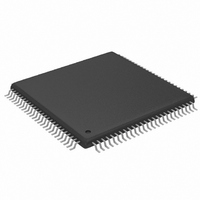
MAX2038CCQ+ Maxim Integrated Products, MAX2038CCQ+ Datasheet

MAX2038CCQ+
Specifications of MAX2038CCQ+
Related parts for MAX2038CCQ+
MAX2038CCQ+ Summary of contents
Page 1
... Optional Individual Channel Drive Capability o 269mW Power Consumption per Channel (Normal Power Mode) and 226mW Power Consumption per Channel (Low-Power Mode) PART MAX2038CCQ+D MAX2038CCQ+TD + Denotes a lead(Pb)-free/RoHS-compliant package Dry packing Tape and reel Exposed pad. * See the Ultrasound-Specific IMD3 Specification in the Applications Applications Information section ...
Page 2
Ultrasound VGA Integrated with CW Octal Mixer ABSOLUTE MAXIMUM RATINGS GND .................................................-0.3V to +5.5V CC REF Any Other Pins to GND...............................-0. Mixer Output Voltage to GND (CW_IOUT+, CW_IOUT-, CW_QOUT+, CW_QOUT-) ................................................13V VGA Differential ...
Page 3
DC ELECTRICAL CHARACTERISTICS—CW MIXER MODE ( Typical Application Circuit , Figure 7. V M4_EN = 0, CW_FILTER = TEST_MODE = CW_VG = 0, CW_M1 = 0, CW_M2 = signals applied, ...
Page 4
Ultrasound VGA Integrated with CW Octal Mixer AC ELECTRICAL CHARACTERISTICS—VGA MODE ( Typical Application Circuit , Figure M4_EN = 0, CW_FILTER = 1, TEST_MODE = CW_VG = 1, CW_M1 = 0, CW_M2 = ...
Page 5
AC ELECTRICAL CHARACTERISTICS—CW MIXER MODE ( Typical Application Circuit , Figure 7. V CW_FILTER = 1, TEST_MODE = CW_VG = 0, CW_M1 = 0, CW_M2 = 0, VG_CLAMP_MODE = 1, f capacitance to GND at each ...
Page 6
Ultrasound VGA Integrated with CW Octal Mixer AC ELECTRICAL CHARACTERISTICS—CW MIXER MODE (continued) ( Typical Application Circuit , Figure 7. V CW_FILTER = 1, TEST_MODE = CW_VG = 0, CW_M1 = 0, CW_M2 = 0, VG_CLAMP_MODE ...
Page 7
4.75V to 5.25V REF the VGA differential outputs is 60pF, differential capacitance across the VGA outputs is 10pF, R values are 5V +25°C, unless otherwise ...
Page 8
Ultrasound VGA Integrated with CW Octal Mixer (Figure 4.75V to 5.25V REF the VGA differential outputs is 60pF, differential capacitance across the VGA outputs is 10pF, R values are ...
Page 9
4.75V to 5.25V REF the VGA differential outputs is 60pF, differential capacitance across the VGA outputs is 10pF, R values are 5V +25°C, unless otherwise ...
Page 10
Ultrasound VGA Integrated with CW Octal Mixer (Figure 4.75V to 5.25V REF = 0, CW_M1 = 0, CW_M2 = 0, CW mixer outputs pulled up to 11V through four separate ±0.1% 115Ω resistors, ...
Page 11
PIN NAME 1 CWIN2- CW Mixer Channel 2 Inverting Differential Input 2 CWIN2+ CW Mixer Channel 2 Noninverting Differential Input 3 VGIN3- VGA Channel 3 Inverting Differential Input 4 VGIN3+ VGA Channel 3 Noninverting Differential Input 5, 10, 19, 24, ...
Page 12
Ultrasound VGA Integrated with CW Octal Mixer PIN NAME +5V Reference Supply. Connect to a low-noise power supply. Bypass to GND with a 0.1µF capacitor as close as possible to the pins. Note that noise performance of the device is ...
Page 13
PIN NAME 70 VGOUT3+ VGA Channel 3 Noninverting Differential Output 71 VGOUT3- VGA Channel 3 Inverting Differential Output 73 LO2 CW LO Input for Channel 2. LO clock input for modes 3 and 4. 74 VGOUT2+ VGA Channel 2 Noninverting ...
Page 14
Ultrasound VGA Integrated with CW Octal Mixer Detailed Description The MAX2038 is an 8-channel VGA integrated with a programmable octal quadrature mixer array designed for ultrasound imaging and Doppler applications. The device is optimized for efficient power consumption, high dynamic ...
Page 15
A clamp is provided to limit the VGA output signals to avoid overdriving the ADC or to prevent ADC satura- tion. Set VG_CLAMP_MODE low to clamp the VGA dif- ferential outputs at 2.4V . Set the VG_CLAMP_MODE P-P high to ...
Page 16
Ultrasound VGA Integrated with CW Octal Mixer CW Mixer Output Summation The outputs from the octal mixer array are summed internally to produce the total CWD summed beam- formed signal. The octal array produces eight differen- tial quadrature (Q) outputs ...
Page 17
The LO_LVDS input frequency operation. The CWD LO frequency range is 1MHz to 7.5MHz, and the input frequency ranges from 8MHz to 60MHz. This high LO clock frequency requires a differ- ential LVDS input. The ...
Page 18
Ultrasound VGA Integrated with CW Octal Mixer CHANNEL DATA_IN CLOCK CHANNEL Figure 1. Data Flow of Serial Shift ...
Page 19
Applications Information Mode Select Response Time The mode select response time is the time that the device takes to switch between CW and VGA modes. One possible approach to interfacing the CW outputs to an instrumentation amplifier used to drive ...
Page 20
Ultrasound VGA Integrated with CW Octal Mixer The serial interface of the MAX2038 programs the LO for 16 quadrature phases using a serial shift register implementation. Data is shifted into the device on DIN. The serial shift ...
Page 21
CW Mixer Output Summation The maximum differential current output is typically 3mA and the mixer output compliance voltage P-P ranges from 4.75V to 12V per mixer channel. The mixer common-mode current in each of the differential mixer outputs is typically ...
Page 22
Ultrasound VGA Integrated with CW Octal Mixer Figure 7. Typical Per-Channel Ultrasound Imaging Application 22 ______________________________________________________________________________________ ...
Page 23
TOP VIEW LO1 76 VGOUT1+ 77 VGOUT1- 78 GND 79 DIN 80 GND CLK 83 CW_M1 84 CW_M2 85 VG_CLAMP_MODE LOAD 88 CW_QOUT+ 89 CW_QOUT- 90 CW_IOUT- 91 CW_IOUT ...
Page 24
... Maxim cannot assume responsibility for use of any circuitry other than circuitry entirely embodied in a Maxim product. No circuit patent licenses are implied. Maxim reserves the right to change the circuitry and specifications without notice at any time. 24 ____________________Maxim Integrated Products, 120 San Gabriel Drive, Sunnyvale, CA 94086 408-737-7600 © 2010 Maxim Integrated Products DESCRIPTION Maxim is a registered trademark of Maxim Integrated Products, Inc ...


