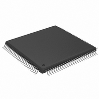
MAX2038CCQ+ Maxim Integrated Products, MAX2038CCQ+ Datasheet - Page 12

MAX2038CCQ+
Manufacturer Part Number
MAX2038CCQ+
Description
IC VGA W/OCTAL MIXER 8CH 100TQFP
Manufacturer
Maxim Integrated Products
Type
Variable Gain Amplifierr
Datasheet
1.MAX2038CCQT.pdf
(24 pages)
Specifications of MAX2038CCQ+
Applications
Medical Ultrasound Imaging, Sonar
Mounting Type
Surface Mount
Package / Case
100-TQFP Exposed Pad, 100-eTQFP, 100-HTQFP, 100-VQFP
Lead Free Status / RoHS Status
Lead free / RoHS Compliant
Ultrasound VGA Integrated
with CW Octal Mixer
12
37, 93
______________________________________________________________________________________
PIN
38
39
40
41
43
44
45
47
48
49
50
51
52
53
55
56
57
59
60
61
62
63
64
65
66
67
68
69
CW_FILTER
LO_LVDS+
LOW_PWR
VGOUT8+
VGOUT7+
VGOUT6+
VGOUT5+
LO_LVDS-
VGOUT4+
VGOUT8-
VGOUT7-
VGOUT6-
VGOUT5-
VG_CTL+
VGOUT4-
EXT_RES
VG_CTL-
CW_VG
M4_EN
NAME
DOUT
V
N.C.
LO8
LO7
LO6
LO5
LO4
LO3
PD
REF
+5V Reference Supply. Connect to a low-noise power supply. Bypass to GND with a 0.1µF capacitor
as close as possible to the pins. Note that noise performance of the device is dependent on the noise
contribution from the supply to V
connected together to share the same supply voltage if the supply for V
External Resistor. Connect a 0.1% 7.5kΩ resistor to ground as close as possible to the pin to set the
bias for the internal biasing circuitry.
CW Mixer VGA Enable. Selects for VGA or CW mixer operation. Set CW_VG to a logic-high to enable
the VGAs while the CW mixers are powered down. Set CW_VG to a logic-low to enable the CW mixers
while the VGAs are powered down.
Power-Down Switch. Drive PD high to set the device in power-down mode. Drive PD low for normal
operation.
CW Filter Mode Corner Frequency Select. Selects in corner frequency of the internal lowpass filter for
the CW path. Set CW_FILTER to a logic-high for a corner frequency of 9.5MHz. Set CW_FILTER to a
logic-low for a corner frequency of 4.5MHz.
Mode 4 Enable. Set M4_EN to a logic-high to override the serial port and activate all 8 channels of the
CW path.
Low-Power Enable. Set high to enable low-power CW mixer mode for the device.
Serial Port Data Output. Data output for ease of daisy-chaining CW channels for analog beamforming
programming.
No Connect. Leave this pin unconnected (this pin is the TEST_MODE pin called out in the MAX2038
EV kit data sheet).
CW LO Input for Channel 8. LO clock input for modes 3 and 4.
VGA Channel 8 Noninverting Differential Output
VGA Channel 8 Inverting Differential Output
CW LO Input for Channel 7. LO clock input for modes 3 and 4.
VGA Channel 7 Noninverting Differential Output
VGA Channel 7 Inverting Differential Output
CW LO Input for Channel 6. LO clock input for modes 3 and 4.
VGA Channel 6 Noninverting Differential Output
VGA Channel 6 Inverting Differential Output
CW LO Input for Channel 5. LO clock input for modes 3 and 4.
VGA Channel 5 Noninverting Differential Output
VGA Channel 5 Inverting Differential Output
VGA Analog Gain Control Differential Input. Set the differential voltage to -2V for maximum gain
(+29.5dB), and to +2V for minimum gain (-12.5dB).
CW LVDS LO Inverting Differential Input. LO clock inverting input for modes 1 and 2.
CW LVDS LO Noninverting Differential Input. LO clock noninverting input for modes 1 and 2.
CW LO Input for Channel 4. LO clock input for modes 3 and 4.
VGA Channel 4 Noninverting Differential Output
VGA Channel 4 Inverting Differential Output
CW LO Input for Channel 3. LO clock input for modes 3 and 4.
REF
. Use a low-noise supply for V
FUNCTION
Pin Description (continued)
REF
. V
CC
CC
exhibits low noise.
and V
REF
can be


