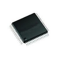
MAX2991ECM+ Maxim Integrated Products, MAX2991ECM+ Datasheet - Page 21

MAX2991ECM+
Manufacturer Part Number
MAX2991ECM+
Description
IC TXRX FRONT-END 48LQFP
Manufacturer
Maxim Integrated Products
Type
General Purposer
Datasheet
1.MAX2991ECM.pdf
(22 pages)
Specifications of MAX2991ECM+
Function
Analog Front-End Transceiver
Interface
SPI Serial
Number Of Circuits
1
Voltage - Supply
3 V ~ 3.6 V
Current - Supply
36mA, 70mA
Power (watts)
1.54W
Operating Temperature
-40°C ~ 85°C
Mounting Type
Surface Mount
Package / Case
48-LQFP
Includes
Automatic Gain Control (AGC)
Product
Analog Front End
Data Rate
1.2 Msps
Interface Type
Digital
Supply Voltage (max)
3.6 V
Supply Voltage (min)
3 V
Supply Current
36 mA, 70 mA
Maximum Operating Temperature
+ 85 C
Minimum Operating Temperature
- 40 C
Maximum Power Dissipation
1535 mW
Mounting Style
SMD/SMT
Number Of Channels
2
Lead Free Status / RoHS Status
Lead free / RoHS Compliant
Table 7. Rx and Tx Filter Adjustment for Different 3dB Frequencies
Table 8. IIR Coefficients for CENELEC A Band (MAX2991 Default Mode)
To program the Rx and Tx filters for different CENELEC
modes, program the filters in narrowband mode and
adjust the cutoff frequency by providing a positive or
negative offset. Typical PTUN2 register values for Rx
and Tx adjustments are given in Table 7. The MAX2991
defaults to the CENELEC A mode.
IIR filters are used in the MAX2991 transmit path to
achieve the desired attenuation at corner and out-of-
band frequencies that comply with regulatory spectral
mask. The filters are implemented as two cascaded
second-order sections (SOS). Each filter implements a
second-order transfer function:
Rx 3dB FREQUENCY
Power-Line Communications (PLC) Integrated
COEFFICIENT NAME
Programming the Integrated IIR Filters
(kHz)
130
140
146
155
IIR0B0
IIR0B1
IIR0B2
IIR0A1
IIR0A2
IIR1B0
IIR1B1
IIR1B2
IIR1A1
IIR1A2
for Different CENELEC Standards
Programming Rx and Tx Filters
______________________________________________________________________________________
Tx 3dB FREQUENCY
FLOATING POINT VALUE
for Different Bands
-0.36787775183970
-1.53137687683985
-1.62702269373124
-1.75120880788804
(kHz)
0.25454609117803
0.25454609117803
0.68982207389294
0.92695273947877
0.92695273947877
0.97809159311434
125
134
140
148
Analog Front-End Transceiver
OFFSET
-15
20
0
9
The coefficients are in Q13 format. For stable/minimum
phase Butterworth IIR filter, the coefficients are between
-2 and +2. Coefficients in the range of -4 to +4 are pos-
sible by using a 16-bit word.
The example in Table 8 shows the design steps used
to generate the coefficients for the filter in CENELEC A
band. For this design, it is desired to get a large attenu-
ation with a sharp corner at around 95kHz. A 4th-order
elliptic filter is used with the 91.9kHz passband fre-
quency. The passband ripple is 1dB and the stopband
attenuation is 12dB. For a 1.2Msps sampling frequency,
the coefficients are shown in Table 8. Note that Q13 rep-
resentation is found by multiplying the floating values by
8192 (2
Q13 FORMAT VALUE
13
-12545
-13329
-14346
-3014
2085
2085
5651
7594
7594
8013
) and rounding the result to an integer.
RXADJ/
TXADJ
79
20
0
9
H(z)
=
B
1 A z
0
+
+
B z
1
TXADJ
1
−
79
20
−
1
0
9
1
+
REGISTER VALUE
+
A z
B z
2
2
−
0x1DAA
0xCBEF
0x1DAA
0xCEFF
0xF43A
0xC7F6
0x1F4D
0x0825
0x0825
0x1613
−
2
2
0x27CF
PTUN2
0x0000
0x0489
0x0A14
21


