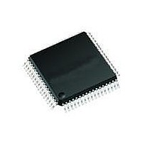
MAX2991ECM+ Maxim Integrated Products, MAX2991ECM+ Datasheet - Page 19

MAX2991ECM+
Manufacturer Part Number
MAX2991ECM+
Description
IC TXRX FRONT-END 48LQFP
Manufacturer
Maxim Integrated Products
Type
General Purposer
Datasheet
1.MAX2991ECM.pdf
(22 pages)
Specifications of MAX2991ECM+
Function
Analog Front-End Transceiver
Interface
SPI Serial
Number Of Circuits
1
Voltage - Supply
3 V ~ 3.6 V
Current - Supply
36mA, 70mA
Power (watts)
1.54W
Operating Temperature
-40°C ~ 85°C
Mounting Type
Surface Mount
Package / Case
48-LQFP
Includes
Automatic Gain Control (AGC)
Product
Analog Front End
Data Rate
1.2 Msps
Interface Type
Digital
Supply Voltage (max)
3.6 V
Supply Voltage (min)
3 V
Supply Current
36 mA, 70 mA
Maximum Operating Temperature
+ 85 C
Minimum Operating Temperature
- 40 C
Maximum Power Dissipation
1535 mW
Mounting Style
SMD/SMT
Number Of Channels
2
Lead Free Status / RoHS Status
Lead free / RoHS Compliant
Table 4. Configuration Bits
The MAX2990’s single write configuration mode allows
sending an arbitrary 16-bit SPI frame to the MAX2991’s
AFE interface. This mode allows configuring the internal
registers without using the host SPI.
The SPI frame has 4 command bits labeled C3, C2,
C1, and C0. These bits are normally set to 0 when
transferring data frames to the DAC. The MAX2991 also
responds to other command codes, shown in Table 4,
Figure 9. Communication Protocol for Indirect Read Access
C3
0
1
1
1
1
1
Power-Line Communications (PLC) Integrated
COMMAND BITS
RXCONV
TXCONV
RXDATA
TXDATA
RXCLK
C2
TXCLK
0
0
0
0
0
1
1
0
C1
X
0
0
1
0
1
16
______________________________________________________________________________________
D0
1
C0
X
0
0
0
1
1
C3
Indirect Write and Read
2
Normal TXDATA packet (C2, C1, and C0 can be used to set the predriver gain dynamically).
Set the Indirect Address register and R/W bit.
Read most significant 8 bits when R/W = 1.
Trigger the indirect register read when R/W = 1.
Write most significant 8 bits to Indirect Data register when R/W = 0.
Read least significant 8 bits when R/W = 1.
Trigger the indirect register read when R/W = 1.
Write least significant 8 bits to Indirect Data register and trigger register write when R/W = 0.
Post increment the Indirect Address in both cases.
Reserved
Reserved
C2
Configuration Mode
3
C1
4
C0
5
Analog Front-End Transceiver
X
6
X
7
X
8
X
to allow reading and writing from/to its host SPI register
space.
The MAX2990 does not support the read configuration
mode of operation, as it cannot set the R/W bit to the
required state. All configuration mode accesses are
treated as writes. Set RDCONFMDEN in the RXCONF
register to logic-high to enable the read configuration
mode. Ensure RXCLK is active during read configura-
tion mode read accesses. The AFE Rx interface must be
inactive during read configuration mode transfers.
9
D7
DESCRIPTION
X
10
D6
X
11
D5
X
12
D4
X
13
D3
X
14
D2
X
15
D1
X
16
D0
X
1
19


