2306-VS KEITHLEY, 2306-VS Datasheet
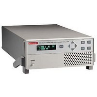
58T8427

2306-VS

Manufacturer Part Number
2306-VS
Description
58T8427
Manufacturer
KEITHLEY
Datasheet

Specifications of 2306-VS

No. Of Outputs
2
Output Voltage
15V
Output Voltage 2
15V
Output Current
5A
Output Current 2
5A
Load Regulation
0.01%
Length
411mm
Width
213mm
Height
89mm
Weight
3.9kg
Power Supply Output Type
Variable
Input Voltage
100VAC To 120VAC / 220VAC To 240VAC
Power Rating
50W
1.888.KEITHLEY
External trigger inputs speed
and simplify control of output
channels
Built-in test sequencing reduces
GPIB bus traffic and improves
test throughput
Ultra-fast response to transient
load currents
Selectable trigger level polarity
Variable output resistance
for simulating battery response
(U.S. Patent No. 6,204,647)
Trigger outputs provided for
event handshaking
100nA DC current sensitivity
Sink up to 3A
Open sense lead detection
Built-in digital voltmeter
2306-VS
w w w.keithley.com
(U.S. only)
these external trigger inputs with built-in test sequencing to create an extremely fast voltage supply
and measurement instrument that minimizes the need for computer and GPIB interaction.
External Triggering Allows High Speed Control of Output Channels
When triggered, the output channels can be instructed to operate at pre-defined voltages or to initi-
ate current, voltage, or pulse current measurements. The availability of two inputs makes it possible
to program each channel to act independently or, if the test developer prefers, to act in parallel. For
example, Channel #1 can be programmed to operate at user-specified voltage levels while Channel
#2 is triggered to take measurements. Measurements are stored in a reading buffer and can be
downloaded to a PC controller after the test routine is complete, minimizing GPIB command and
data transfer delays. Trigger outputs indicate event completion, allowing users to minimize step
delays between trigger-in sequences.
External triggering also allows the Model 2306-VS to exercise tight control over signal capture timing
for greater measurement and load condition coordination. As a result, manufacturers can achieve
greater confidence in their own compliance testing and can offer their customers more accurate com-
ponent specifications.
This precision power supply has ultra-fast transient response to duplicate the output characteristics
of actual batteries. In response to large load changes, voltage droops on the Model 2306-VS’s battery
channel are less than 100mV and transient recovery times are less than 60µs, even when the instru-
ment is used with long test leads. The Model 2306-VS also employs a unique variable output resist-
ance so that the voltage output can emulate a battery’s true response (U.S. Patent No. 6,204,647). By
providing stable output voltage, a device-under-
test (DUT) can transition from standby power
(low current) to RF transmission (high current)
seamlessly without nuisance tripping.
Built-in Test Sequencing
Maximizes Throughput
The Model 2306-VS’s built-in test sequencing
capabilities allow setting up and executing
up to 20 individual voltage and measurement
sequences. By minimizing the need to transfer
instrument commands or data over the GPIB
Dual-Channel Battery/Charger
Simulator with External Triggering
A
G R E A T E R
M E A S U R E
The dual-channel Model 2306-VS Battery/
Charger Simulator with External Triggering is
designed specifically for development and high
speed production testing of DC battery-operated
products, such as cellular handsets, cellular com-
ponents like RFIC power amplifiers, and other
high volume precision electrical components
that require a DC voltage supply. Like Keithley’s
original single- channel Model 2302 Battery
Simulator and dual-channel Model 2306 Battery/
Charger Simulator, this precision power supply
has ultra-fast transient response to provide out-
put characteristics identical to actual batteries.
However, in addition to the capabilities offered
by these models, the Model 2306-VS (voltage
step) provides two external trigger inputs, which
allow independent control of the instrument’s
output channels. These trigger inputs speed and
simplify control of the output channels by elimi-
nating the time lags associated with GPIB data
communications. The Model 2306-VS combines
APPLICATIONS
Development and high speed
testing of DC battery-operated
products, such as:
• Cellular handsets
• Cellular components like RFIC
• Other high volume precision
O F
power amplifiers
electrical components
C O N F I D E N C E

Related parts for 2306-VS

2306-VS Summary of contents

Page 1

... The Model 2306-VS also employs a unique variable output resist- ance so that the voltage output can emulate a battery’s true response (U.S. Patent No. 6,204,647). By ...

Page 2

... Trigger voltage setpoints on Channel #1 while triggering Channel #2 measurement readings 1.5V 1.0V 0.5V 0V 200µs/Div. Figure 1. This graph illustrates Channel #1 output voltage response times based on a four-point voltage step sequence (0.5V/1.0V/1.5V/0.5V). The Model 2306-VS can complete this sequence within 1.5ms. 600mV 400mV 200mV 0mV 40µs/Div. Figure 2. This magnified view of the first 500mV voltage step from the signal shown in Figure 1 illustrates how the Channel #1 output reaches the voltage setpoint within 160µ ...

Page 3

... The Model 2306-VS also eliminates the large stabilizing capacitors needed at the DUT to compensate for the large voltage droop that occurs when testing with conventional power supplies. By varying the output resist ance, which can be done while the output is turned on, test engineers can simulate the operation of different battery types as well as batteries nearing the end of their useful lives ...

Page 4

... Output #1 (Battery) DC VOLTAGE OUTPUT (2 Years, 23°C ± 5°C) OUTPUT VOLTAGE +15VDC. OUTPUT ACCURACY: ±(0.05% + 3mV). PROGRAMMING RESOLUTION: 1mV. READBACK ACCURACY : ±(0.05% + 3mV). 1 READBACK RESOLUTION: 1mV. LOAD REGULATION: ±(0.01% + 2mV). LINE REGULATION: ±0.5mV. STABILITY : ±(0.01% + 0.5mV). 2 MEASUREMENT TIME CHOICES: 0. PLC ...

Page 5

... Output #2 (Charger) DC VOLTAGE OUTPUT (2 Years, 23°C ± 5°C) OUTPUT VOLTAGE +15VDC. OUTPUT ACCURACY: ±(0.05% + 10mV). PROGRAMMING RESOLUTION: 10mV. READBACK ACCURACY : ±(0.05% + 3mV). 1 READBACK RESOLUTION: 1mV. OUTPUT VOLTAGE SETTLING TIME: 5ms to within stated accuracy. LOAD REGULATION: ±(0.01% + 2mV). ...

Page 6

... Voltage Stepping Only TEST CONDITIONS: 1. Trigger external is enabled on both channels. 2. Only a single channel is externally triggered during the sequence while remaining channel stays idle. 3. Times based on 0 programmable user delay. Channel Trigger In Output Voltage Channel Trigger Out Output #1 (Battery) Output #2 (Charger µ ...

Page 7

... Voltage Stepping Both Channels With Channel 2 TEST CONDITIONS: 1. Only a single channel is externally triggered during the sequence while remaining channel stays idle. 2. Times based on 0 programmable user delay. Channel 2 Trigger In Output Voltage Channel 2 Output Voltage Channel 1 Channel 2 Trigger Out Output #1 (Battery)/Output #2 (Charger µ ...

Page 8

... GENERAL ISOLATION (LOW–EARTH): 22VDC max. Do not exceed 60VDC between any two terminals of either connector. PROGRAMMING: IEEE-488.2 (SCPI). USER-DEFINABLE POWER-UP STATES: 3. REAR PANEL CONNECTORS: Two trigger in and two trigger out (BNC) connectors. Two 8- position quick disconnect terminal block for output (4), sense (2), and DVM (2). ...

Related keywords