2306-PJ KEITHLEY, 2306-PJ Datasheet
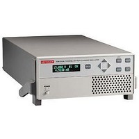
58T8425

2306-PJ

Manufacturer Part Number
2306-PJ
Description
58T8425
Manufacturer
KEITHLEY
Datasheet

Specifications of 2306-PJ

No. Of Outputs
2
Output Voltage
15V
Output Voltage 2
15V
Output Current
5A
Output Current 2
5A
Load Regulation
0.01%
Length
411mm
Width
213mm
Height
89mm
Weight
3.2kg
Power Supply Output Type
Variable
Input Voltage
100VAC To 120VAC / 220VAC To 240VAC
Power Rating
50W
2302-3Y-EW
2306-3Y-EW
2306-PJ-3Y-EW
C/2302-3Y-ISO
C/2306-3Y-ISO
*Not available in all countries
1.888.KEITHLEY
2302
2306, 2306-PJ
Ultrafast response to transient
load currents
Choice of single- or dual-
channel supplies
Optimized for development
and testing of battery-powered
devices
Variable output resistance
for simulating battery response
(U.S. Patent No. 6,204,647)
Pulse peak, average, and
baseline current measurements
100nA DC current sensitivity
Current step measure function
Sink up to 3A
Open sense lead detection
Built-in digital voltmeter
w w w.keithley.com
SERVICES AVAILABLE
1-year factory warranty extended to 3 years
from date of shipment
1-year factory warranty extended to 3 years
from date of shipment
1-year factory warranty extended to 3 years
from date of shipment
3 (ISO-17025 accredited) calibrations within 3
years of purchase for Model 2302*
3 (ISO-17025 accredited) calibrations within 3
years of purchase for Models 2306, 2306-P*
(U.S. only)
to operate like a discharged rechargeable battery, sinking current from a separate charger or from the
Model 2306’s charger- simulator channel.
Maximize Test Throughput with Accurate Battery Simulation
The battery-output channels of the Models 2302 and 2306 are designed to simulate the output
response of a battery. This capability, combined with their fast transient response, makes it possible
to power the device during testing in exactly the
same way as a battery will power the device
during actual use. The output resistance of the
Model 2302’s and the Model 2306’s battery chan-
nel can be programmed (with 10mW resolution)
over the range from 0W to 1W so that the out-
put resistance can be set to the same level as the
output resistance of the battery that powers the
device. See Figure 1.
Portable wireless devices make great demands
on their battery power sources. The battery must
source load currents that can jump virtually
instantaneously from a standby current level
(100–300mA) to a full-power RF transmission
current level (1–3A). In other words, the load
current on the battery can increase rapidly by
a factor of 700–1000%. As a result, the battery
voltage drops by an amount equal to the value
of the current change multiplied by the battery’s
internal resistance. The Models 2302 and 2306
power supplies enable test systems to duplicate
this voltage drop by programming their output
resistance to be equivalent to that of the battery
that will power the device. This allows wire-
less device manufacturers to test their products
under the same power conditions that they will
encounter in actual use. (See Figure 2.)
Battery Simulator
Battery/Charger Simulators
A
G R E A T E R
M E A S U R E
The single-channel Model 2302 Battery
Simulator and dual-channel Model 2306 Battery/
Charger Simulator were designed specifically for
development and test applications of portable,
battery-operated products, such as cellular and
cordless telephones, mobile radios, and pagers.
These precision power supplies have ultrafast
transient response so they can have output
characteristics identical to actual batteries.
These supplies employ a unique variable output
resistance so the voltage output can emulate a
battery’s response (U.S. Patent No. 6,204,647).
They provide stable voltage outputs, even when
a device-under-test (DUT) makes the rapid tran-
sition from the standby (low current) state to the
RF transmission (high current) state. In addition,
they can monitor DUT power consumption by
meas uring both DC currents and pulse load cur-
rents. The Model 2302’s and the Model 2306’s
battery-simulator channel can be programmed
Figure 1. Simplified schematic of a battery
and the 2302/2306.
CABLES
7007-1
7007-2
SC-182
RACK MOUNT KITS
4288-1
4288-2
IEEE-488 INTERFACES
KPCI-488LPA
KUSB-488B
R
INT
O F
V
Battery
ACCESSORIES AVAILABLE
C O N F I D E N C E
+
Shielded IEEE-488 Cable, 1m (3.3 ft)
Shielded IEEE-488 Cable, 2m (6.6 ft)
Low-Inductance Coaxial Cable (42nH/ft)
Single Fixed Rack Mount Kit
Dual Fixed Rack Mount Kit
IEEE-488 Interface/Controller for the PCI Bus
IEEE-488 USB-to-GPIB Interface Adapter
R
OUT
V
2302/2306
+

Related parts for 2306-PJ

2306-PJ Summary of contents

Page 1

... Ultrafast response to transient load currents • Choice of single- or dual- channel supplies • Optimized for development and testing of battery-powered devices • Variable output resistance for simulating battery response (U.S. Patent No. 6,204,647) • Pulse peak, average, and baseline current measurements • ...

Page 2

... Ordering Information 2302 Battery Simulator 2306 Dual-Channel Battery/ Charger Simulator 2306-PJ Dual-Channel Battery/ Charger Simulator with 500mA Range Accessories Supplied User and service manuals, CS-846 output connectors mating terminal Conventional Power Supplies and Wireless Device Testing During production testing, supplying ...

Page 3

... Battery Terminals Figure 5. For charger control circuit testing applications, the Model 2306 and 2306-PJ can provide the functions of both a charger- simulating source and a discharged battery simulator. the output voltage does not change from the programmed level, which could cause production devices to be improperly calibrated, the user can set high and low limits around the desired voltage level ...

Page 4

... Battery Simulator Battery/Charger Simulators ISOLATION (low–earth): 22V DC max. For Models 2306 and 2306-PJ, do not exceed 60V DC between any two terminals of either connector. PROGRAMMING: IEEE-488.2 (SCPI). USER-DEFINABLE POWER-UP STATES for Model 2306-PJ). REAR PANEL CONNECTORS: Two (one for Model 2302) 8-position quick disconnect termi- nal block for output (4), sense (2), and DVM (2). TEMPERATURE COEFFICIENT (outside 23° ...

Page 5

... NUMBER OF SAMPLES 5000. TRANSFER SAMPLES ACROSS IEEE BUS IN BINARY MODE: 4800 bytes/s, typical. LONG INTEGRATION MODE CURRENT MEASUREMENT 2302, 2306: Available on 5A range only. 2306-PJ: Available on 5A and 500mA current ranges. MEASUREMENT TIME 6 : 850ms (840ms seconds in 1ms steps. DIGITAL VOLTMETER INPUT (2 Years, 23°C ± 5°C) INPUT VOLTAGE RANGE: – ...

Page 6

... OUTPUT #2 (CHARGER) DC VOLTAGE OUTPUT (2 Years, 23°C ± 5°C) OUTPUT VOLTAGE +15V DC. OUTPUT ACCURACY: ±(0.05% + 10mV). PROGRAMMING RESOLUTION: 10mV. READBACK ACCURACY : ±(0.05% + 3mV). 1 READBACK RESOLUTION: 1mV. OUTPUT VOLTAGE SETTLING TIME: 5ms to within stated accuracy. LOAD REGULATION: 0.01% + 2mV. ...

Related keywords