2306 KEITHLEY, 2306 Datasheet - Page 6
2306
Manufacturer Part Number
2306
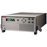
Description
58T8423
Manufacturer
KEITHLEY
Specifications of 2306
No. Of Outputs
2
Output Voltage
15V
Output Voltage 2
15V
Output Current
5A
Output Current 2
5A
Load Regulation
0.01%
Length
411mm
Width
213mm
Height
89mm
Weight
3.2kg
Power Supply Output Type
Variable
Input Voltage
100VAC To 120VAC / 220VAC To 240VAC
Power Rating
50W
Available stocks
Company
Part Number
Manufacturer
Quantity
Price
Company:

Part Number:
2306019201W
Manufacturer:
AGILENT
Quantity:
336
Company:
Part Number:
23061-1V
Manufacturer:
HRS
Quantity:
2 000
Part Number:
230619121242
Manufacturer:
VISHAY/威世
Quantity:
20 000
Part Number:
230619121302
Manufacturer:
VISHAY/威世
Quantity:
20 000
Part Number:
230619124752
Manufacturer:
VISHAY/威世
Quantity:
20 000
Company:
Part Number:
230622
Manufacturer:
BSI
Quantity:
30 000
Company:
Part Number:
2306566
Manufacturer:
Phoenix Contact
Quantity:
275


2302
2306, 2306-PJ
OUTPUT #2 (CHARGER)
DC VOLTAGE OUTPUT (2 Years, 23°C ± 5°C)
OUTPUT VOLTAGE: 0 to +15V DC.
OUTPUT ACCURACY: ±(0.05% + 10mV).
PROGRAMMING RESOLUTION: 10mV.
READBACK ACCURACY
READBACK RESOLUTION: 1mV.
OUTPUT VOLTAGE SETTLING TIME: 5ms to within stated accuracy.
LOAD REGULATION: 0.01% + 2mV.
LINE REGULATION: 0.5mV.
STABILITY
MEASUREMENT TIME CHOICES: 0.01 to 10PLC
AVERAGE READINGS: 1 to 10.
READING TIME
TRANSIENT RESPONSE:
REMOTE SENSE: 1V max. drop in each lead. Add 2mV to the voltage load regulation specification for
DC CURRENT (2 Years, 23°C ± 5°C)
CONTINUOUS AVERAGE OUTPUT CURRENT:
CONTINUOUS AVERAGE SINK CURRENT:
SOURCE COMPLIANCE ACCURACY: ±(0.16% + 5mA)
PROGRAMMED SOURCE COMPLIANCE RESOLUTION: 1.25mA.
READBACK ACCURACY
READBACK RESOLUTION: 5A Range: 100µA.
LOAD REGULATION: 0.01% + 1mA.
LINE REGULATION: 0.5mA.
STABILITY
MEASUREMENT TIME CHOICES: 0.01 to 10PLC
AVERAGE READINGS: 1 to 10.
READING TIME
Transient Recovery Time
Transient Voltage Drop
each 1V change in the negative output lead due to load current change. Remote sense required.
Integrity of connection continually monitored. If compromised, output will turn off automatically
once settable window (±0 to ±8V) around normal voltage exceeded.
Channel #1 (Battery) OFF:
Channel #1 (Battery) ON:
Peak currents can be a maximum of 5A provided the average current is within the above limits.
Channel #1 (Battery) OFF:
Channel #1 (Battery) ON:
I = 50W/(V
I = (50W – Power consumed by channel #1)/(V
The power consumed by channel #1 is calculated as:
0–5V: 3A max.
5–15V: Derate 0.2A per volt above 5V. Compliance setting controls sinking.
Available current = (50W – Power consumed by channel #1)/5; 3A max. (0–5V).
Derate 0.2A per volt above 5V.
1.888.KEITHLEY
Channel #1 sourcing current:
Channel #1 sinking current:
w w w.keithley.com
2
Power consumed = (V
Power consumed = 5 × (sink current)
4
: 0.01% + 0.5mV.
: 0.01% + 50µA.
SET
1, 8, 9
1, 8, 9
channel 2 + 6V); 5A max.
: 31ms, typical.
: 31ms, typical.
1
1
: ±(0.05% + 3mV).
:
13
5A Range: ±(0.2% + 200µA).
5mA Range: ±(0.2% + 1µA).
5mA Range: 0.1µA.
SET
channel 1 + 6V) × (current supplied)
<120mV
High Bandwidth
<50µs
(U.S. only)
3
3
or <80µs
7
or <150mV
7
, in 0.01PLC steps.
, in 0.01PLC steps.
SET
5
channel 2 + 6V); 5A max.
.
4
4
<160mV
Battery Simulator
Battery/Charger Simulators
Low Bandwidth
<60µs
3
3
or <100µs
or <200mV
4
4
A
PULSE CURRENT MEASUREMENT OPERATION
TRIGGER LEVEL: 5mA to 5A, in 5mA steps.
TRIGGER DELAY: 0 to 100ms, in 10µs steps.
INTERNAL TRIGGER DELAY: 15µs.
HIGH/LOW/AVERAGE MODE:
PULSE CURRENT MEASUREMENT ACCURACY
BURST MODE CURRENT MEASUREMENT
MEASUREMENT APERTURE: 33.3µs.
CONVERSION RATE: 2040/second, typical.
INTERNAL TRIGGER DELAY: 15µs.
NUMBER OF SAMPLES: 1 to 5000.
TRANSFER SAMPLES ACROSS IEEE BUS IN BINARY MODE: 4800 bytes/s, typical.
LONG INTEGRATION MODE CURRENT MEASUREMENT
MEASUREMENT TIME
DIGITAL VOLTMETER INPUT (2 Years, 23°C ± 5°C)
INPUT VOLTAGE RANGE: –5 to +30V DC.
INPUT IMPEDANCE: 2MW typical.
MAXIMUM VOLTAGE (either input terminal) WITH RESPECT TO OUTPUT LOW: –5V, +30V.
READING ACCURACY
READING RESOLUTION: 1mV.
CONNECTOR: HI and LO input pair part of Output #2’s terminal block.
MEASUREMENT TIME CHOICES: 0.01 to 10PLC
AVERAGE READINGS: 1 to 10.
READING TIME
NOTES
1. PLC = 1.00.
2. Following 15 minute warm-up, the change in output over 8 hours under ambient temperature, constant load,
3. Remote sense, at output terminals, 0.5A to 5A typical.
4. Remote sense, with 4.5m (15 ft) of 16 gauge (1.31mm2) wire and 1W resistance in each lead to simulate typical
5. Minimum current in constant current mode is 6mA.
6. 60Hz (50Hz).
7. PLC = Power Line Cycle. 1PLC = 16.7ms for 60Hz operation, 20ms for 50Hz operation. Display off.
9. Speed includes measurement and binary data transfer out of GPIB.
10. Typical values, peak-to-peak noise equals 6 times rms noise.
11. Based on settled signal: 100µs pulse trigger delay.
12. Also applies to other apertures that are integer multiples of 1PLC.
13. Recovery to within 20mV of previous level.
G R E A T E R
500 µs – <1 PLC
100 µs – 200 µs
200 µs – 500 µs
and line operating conditions.
test environment, 1.5A load change (0.15A to 1.65A).
Measurement Aperture Settings: 33.3µs to 833ms, in 33.3µs steps.
Average Readings: 1 to 100.
Aperture
<100 µs
>1 PLC
1 PLC
12
1, 8, 9
M E A S U R E
: 31ms, typical.
6
1
: 850ms (840ms) to 60 seconds in 1ms steps.
: ±(0.05% + 3mV).
±(% reading + offset + rms noise
0.2% + 900 µA +
0.2% + 900 µA +
0.2% + 900 µA +
0.2% + 600 µA +
0.2% + 400 µA +
0.2% + 400 µA + 100 µA
O F
C O N F I D E N C E
Accuracy
11
7
(2 Years, 23°C ±5°C):
, in 0.01PLC steps.
2 mA
1.5 mA
1 mA
0.8 mA
0 mA
10
)
Related parts for 2306
Image
Part Number
Description
Manufacturer
Datasheet
Request
R


Part Number:
Description:
KEITHLY SINGLE FIXED RACK MOUNT
Manufacturer:
KEITHLEY
Datasheet:
Part Number:
Description:
KEITHLY MULTIPLEXER DIGITAL I/O MODULE
Manufacturer:
KEITHLEY
Datasheet:
