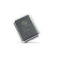
PI7C8140AMAE Pericom Semiconductor, PI7C8140AMAE Datasheet - Page 23

PI7C8140AMAE
Manufacturer Part Number
PI7C8140AMAE
Description
IC PCI-PCI BRIDGE 2PORT 128-QFP
Manufacturer
Pericom Semiconductor
Datasheet
1.PI7C8140AMAE.pdf
(82 pages)
Specifications of PI7C8140AMAE
Applications
*
Interface
*
Voltage - Supply
*
Package / Case
128-QFP
Mounting Type
Surface Mount
Maximum Operating Temperature
+ 85 C
Minimum Operating Temperature
0 C
Mounting Style
SMD/SMT
Operating Supply Voltage
3 V to 3.6 V
Supply Current (max)
230 mA
Lead Free Status / RoHS Status
Lead free / RoHS Compliant
Available stocks
Company
Part Number
Manufacturer
Quantity
Price
Company:
Part Number:
PI7C8140AMAE
Manufacturer:
Pericom
Quantity:
135
Company:
Part Number:
PI7C8140AMAE
Manufacturer:
SONY
Quantity:
469
Part Number:
PI7C8140AMAE
Manufacturer:
PERICOM
Quantity:
20 000
07-0067
2.6.6 DELAYED READ COMPLETION WITH TARGET
2.6.7 DELAYED READ COMPLETION ON INITIATOR BUS
required to continue to repeat the same read transaction until at least one data transfer is completed, or
until a target response (target abort or master abort) other than a target retry is received.
When delayed read request reaches the head of the delayed transaction queue, the bridge arbitrates for
the target bus and initiates the read transaction only if all previously queued posted write transactions
have been delivered. The bridge uses the exact read address and read command captured from the
initiator during the initial delayed read request to initiate the read transaction. If the read transaction is a
non-prefetchable read, the bridge drives the captured byte enable bits during the next cycle. If the
transaction is a prefetchable read transaction, it drives all byte enable bits to zero for all data phases. If
the bridge receives a target retry in response to the read transaction on the target bus, it continues to
repeat the read transaction until at least one data transfer is completed, or until an error condition is
encountered. If the transaction is terminated via normal master termination or target disconnect after at
least one data transfer has been completed, the bridge does not initiate any further attempts to read more
data.
If the bridge is unable to obtain read data from the target after 2
the bridge will report system error. The number of attempts is programmable. The bridge also asserts
P_SERR# if the primary SERR# enable bit is set in the command register. See Section 5.4 for
information on the assertion of P_SERR#.
Once the bridge receives DEVSEL# and TRDY# from the target, it transfers the data read to the
opposite direction read data queue, pointing toward the opposite inter-face, before terminating the
transaction. For example, read data in response to a downstream read transaction initiated on the
primary bus is placed in the upstream read data queue. The bridge can accept one DWORD of read data
each PCI clock cycle; that is, no master wait states are inserted. The number of DWORD’s transferred
during a delayed read transaction depends on the conditions given in Table 2-4 (assuming no disconnect
is received from the target).
When the transaction has been completed on the target bus, and the delayed read data is at the head of
the read data queue, and all ordering constraints with posted write transactions have been satisfied, the
bridge transfers the data to the initiator when the initiator repeats the transaction. For memory read
transactions, the bridge aliases the memory read, memory read line, and memory read multiple bus
commands when matching the bus command of the transaction to the bus command in the delayed
transaction queue. The bridge returns a target disconnect along with the transfer of the last DWORD of
read data to the initiator. If the bridge initiator terminates the transaction before all read data has been
transferred, the remaining read data left in data buffers is discarded.
When the master repeats the transaction and starts transferring prefetchable read data from data buffers
while the read transaction on the target bus is still in progress and before a read boundary is reached on
the target bus, the read transaction starts operating in flow-through mode. Because data is flowing
through the data buffers from the target to the initiator, long read bursts can then be sustained. In this
case, the read transaction is allowed to continue until the initiator terminates the transaction, or until an
aligned 4KB address boundary is reached, or until the buffer fills, whichever comes first. When the
buffer empties, the bridge reflects the stalled condition to the initiator by disconnecting the initiator
with data. The initiator may retry the transaction later if data are needed. If the initiator does not need
any more data, the initiator will not continue the disconnected transaction. In this case, the bridge will
Page 23 of 82
24
(default) or 2
2-PORT PCI-TO-PCI BRIDGE
March 20, 2007 – Revision 1.01
32
(maximum) attempts,
PI7C8140A


