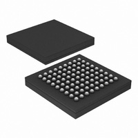
PX1011B-EL1/G,551 NXP Semiconductors, PX1011B-EL1/G,551 Datasheet - Page 6

PX1011B-EL1/G,551
Manufacturer Part Number
PX1011B-EL1/G,551
Description
IC PCI-EXPRESS X1 PHY 81-LFBGA
Manufacturer
NXP Semiconductors
Specifications of PX1011B-EL1/G,551
Package / Case
81-LFBGA
Applications
PCI Express MAX to PCI Express PHY
Interface
JTAG
Voltage - Supply
1.2 V
Mounting Type
Surface Mount
Input Voltage Range (max)
0.31 V
Maximum Operating Temperature
+ 70 C
Maximum Power Dissipation
300 mW
Minimum Operating Temperature
0 C
Mounting Style
SMD/SMT
Operating Supply Voltage
1.2 V
Supply Current (max)
28 mA
Lead Free Status / RoHS Status
Lead free / RoHS Compliant
Lead Free Status / RoHS Status
Lead free / RoHS Compliant, Lead free / RoHS Compliant
Other names
568-4715
935282113551
PX1011B-EL1/G-S
PX1011B-EL1/G-S
935282113551
PX1011B-EL1/G-S
PX1011B-EL1/G-S
Available stocks
Company
Part Number
Manufacturer
Quantity
Price
Company:
Part Number:
PX1011B-EL1/G,551
Manufacturer:
NXP Semiconductors
Quantity:
10 000
NXP Semiconductors
PX1011B_4
Product data sheet
7.2 Pin description
The PHY input and output pins are described in
output is defined from the perspective of the PHY. Thus a signal on a pin described as an
output is driven by the PHY and a signal on a pin described as an input is received by the
PHY. A basic description of each pin is provided.
Table 5.
Table 6.
Table 7.
Table 8.
Symbol
RX_P
RX_N
TX_P
TX_N
Symbol
TXDATA[7:0]
TXDATAK
Symbol
RXDATA[7:0]
RXDATAK
Symbol
RXDET_ LOOPB
TXIDLE
TXCOMP
RXPOL
RESET_N
PWRDWN0
PWRDWN1
PCI Express serial data lines
PXPIPE interface transmit data signals
PXPIPE interface receive data signals
PXPIPE interface command signals
Pin
E1
F1
H1
J1
Pin
J9, H9, G8, G9,
F8, F9, E9, D9
J7
Pin
B3, A3, B4, A4,
A5, B6, A6, B7
A7
Pin
H7
H4
J5
J4
J3
H6
J6
Rev. 04 — 4 September 2009
Type
input
input
input
input
input
input
input
Type
input
input
output
output
Type
input
input
Type
output
output
Signaling
SSTL_2
SSTL_2
SSTL_2
SSTL_2
SSTL_2
SSTL_2
SSTL_2
Signaling
PCIe I/O
PCIe I/O
PCIe I/O
PCIe I/O
Signaling
SSTL_2
SSTL_2
Signaling
SSTL_2
SSTL_2
Description
used to tell the PHY to begin a receiver
detection operation or to begin loopback;
LOW = reset state
forces TX output to electrical idle. TXIDLE
should be asserted while in power states P0s
and P1.
used when transmitting the compliance
pattern; HIGH-level sets the running disparity
to negative
signals the PHY to perform a polarity inversion
on the receive data; LOW = PHY does no
polarity inversion; HIGH = PHY does polarity
inversion
PHY reset input; active LOW
transceiver power-up and power-down inputs
(see
Table 5
Table
Description
differential input receive pair with 50
on-chip termination
differential output transmit pair with
50
Description
8-bit transmit data input from the MAC
to the PHY
selection input for the symbols of
transmit data; LOW = data byte;
HIGH = control byte
Description
8-bit receive data output from the PHY
to the MAC
selection output for the symbols of
receive data; LOW = data byte;
HIGH = control byte
PCI Express stand-alone X1 PHY
to
13); 0x2 = reset state
Table
on-chip termination
12. Note that input and
PX1011B
© NXP B.V. 2009. All rights reserved.
6 of 30


