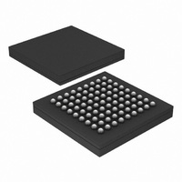
PX1011B-EL1/G,551 NXP Semiconductors, PX1011B-EL1/G,551 Datasheet - Page 20

PX1011B-EL1/G,551
Manufacturer Part Number
PX1011B-EL1/G,551
Description
IC PCI-EXPRESS X1 PHY 81-LFBGA
Manufacturer
NXP Semiconductors
Specifications of PX1011B-EL1/G,551
Package / Case
81-LFBGA
Applications
PCI Express MAX to PCI Express PHY
Interface
JTAG
Voltage - Supply
1.2 V
Mounting Type
Surface Mount
Input Voltage Range (max)
0.31 V
Maximum Operating Temperature
+ 70 C
Maximum Power Dissipation
300 mW
Minimum Operating Temperature
0 C
Mounting Style
SMD/SMT
Operating Supply Voltage
1.2 V
Supply Current (max)
28 mA
Lead Free Status / RoHS Status
Lead free / RoHS Compliant
Lead Free Status / RoHS Status
Lead free / RoHS Compliant, Lead free / RoHS Compliant
Other names
568-4715
935282113551
PX1011B-EL1/G-S
PX1011B-EL1/G-S
935282113551
PX1011B-EL1/G-S
PX1011B-EL1/G-S
Available stocks
Company
Part Number
Manufacturer
Quantity
Price
Company:
Part Number:
PX1011B-EL1/G,551
Manufacturer:
NXP Semiconductors
Quantity:
10 000
NXP Semiconductors
11. Characteristics
Table 18.
PX1011B_4
Product data sheet
Symbol
Supplies
V
V
V
V
V
V
I
I
I
I
I
I
Receiver
UI
V
t
V
Z
Z
RL
RL
t
t
t
Reference clock
f
f
V
V
Z
DDD1
DDD2
DDD3
DD
DDA1
DDA2
RX_MAX_JITTER
lock(CDR)(ref)
lock(CDR)(data)
RX_latency
clk(ref)
mod(clk)(ref)
RX_DC
RX_HIGH_IMP_DC
f
C-DC
DDD1
DDD2
DDD3
DD
DDA1
DDA2
RX_DIFFp-p
IDLE_DET_DIFFp-p
IH(se)REFCLK
IL(se)REFCLK
mod(clk)(ref)
RX_DIFF
RX_CM
PCI Express PHY characteristics
Parameter
digital supply voltage 1
digital supply voltage 2
digital supply voltage 3
supply voltage
analog supply voltage 1
analog supply voltage 2
digital supply current 1
digital supply current 2
digital supply current 3
supply current
analog supply current 1
analog supply current 2
unit interval
differential input peak-to-peak voltage
maximum receiver jitter time
electrical idle detect threshold
DC input impedance
powered-down DC input impedance
differential return loss
common mode return loss
CDR lock time (reference loop)
CDR lock time (data loop)
receiver latency
reference clock frequency
reference clock modulation frequency
range
reference clock modulation frequency
REFCLK single-end HIGH-level input
voltage
REFCLK single-end LOW-level input
voltage
clock source DC impedance
Rev. 04 — 4 September 2009
Conditions
for JTAG I/O
for SSTL_2 I/O
for core
for high-speed serial I/O
and PVT
for serializer
for serializer
for JTAG I/O
for SSTL_2; no load
for core
for high-speed serial I/O
and PVT
for serializer
for serializer
1 clock cycle is 4 ns
PCI Express stand-alone X1 PHY
Min
3.0
2.3
1.15
1.15
1.15
3.0
0.1
-
5
15
15
7
399.88 400
0.175
-
65
40
200
15
6
-
-
6
99.97
30
-
40
0.5
0.3
Typ
3.3
2.5
1.2
1.2
1.2
3.3
1
24
10
20
20
10
-
-
-
50
-
-
-
-
-
-
100
-
-
0.7
0
50
PX1011B
© NXP B.V. 2009. All rights reserved.
Max
3.6
2.7
1.3
1.3
1.3
3.6
2
35
15
28
28
15
400.12 ps
1.2
0.6
175
60
-
-
-
50
2.5
13
100.03 MHz
+0
33
1.15
-
60
20 of 30
Unit
V
V
V
V
V
V
mA
mA
mA
mA
mA
mA
V
UI
mV
k
dB
dB
clock
cycle
%
kHz
V
V
s
s


