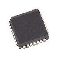
AMIS49587C5871RG ON Semiconductor, AMIS49587C5871RG Datasheet - Page 30

AMIS49587C5871RG
Manufacturer Part Number
AMIS49587C5871RG
Description
IC MODEM PLC 50/60MHZ 28PLCC
Manufacturer
ON Semiconductor
Specifications of AMIS49587C5871RG
Baud Rates
Selectable
Interface
SCI
Voltage - Supply
3 V ~ 3.6 V
Mounting Type
Surface Mount
Package / Case
28-PLCC
Number Of Transmitters
1
Power Supply Requirement
Single
Package Type
PLCC
Operating Temperature Classification
Commercial
Mounting
Surface Mount
Pin Count
28
Operating Temperature (max)
70C
Dual Supply Voltage (typ)
Not RequiredV
Dual Supply Voltage (max)
Not RequiredV
Dual Supply Voltage (min)
Not RequiredV
Lead Free Status / RoHS Status
Lead free / RoHS Compliant
Data Format
-
Lead Free Status / Rohs Status
Compliant
Available stocks
Company
Part Number
Manufacturer
Quantity
Price
Company:
Part Number:
AMIS49587C5871RG
Manufacturer:
ON
Quantity:
3 400
Company:
Part Number:
AMIS49587C5871RG
Manufacturer:
ON Semiconductor
Quantity:
10 000
RESET AND SYNCHRO COMMANDS
Description
AMIS−49587 to the Base Micro to indicate the changes in the synchronization state of the AMIS−49587.
Synchro_Indication (Tag 10h)
Description: The Synchro_Indication is sent by the AMIS−49587 in order to indicate that something has changed in the
synchronization state. The field Synchro_Data contains the change reason (see Section Synchronization State Codes) and data
corresponding with this change.
Table 34. GENERAL DESCRIPTION OF SYNCHRO_INDICATION
Synchronisation Found (01h)
Synchronisation Confirmed (02h)
Synchronisation Lost (04h)
Time−out not addressed has expired
(01h)
Time−out frame not OK has expired
(02h)
Time−out synchro confirm has expired
(03h)
Addressed by a wrong initiator
(04h)
External desynchro command
(05h)
Search Initiator active
(06h)
Syntax:
The reset command is used to replace the AMIS−49587 in the Not Set mode. The synchro commands are sent by the
AMIS−49587
Initiator
Change Reason Field
Frame Format:
<STX>
Synchro_Indication (Synchro_Data)
Command (arguments)
Master/Slave
Length
1 byte: Pad
2 bytes: Signal S0
2 bytes: Noise N0
2 bytes: Signal S1
2 bytes: Noise N1
2 bytes: ASK Threshold or FSK factor
1 byte : Method
1 byte : Synchro−Bit and Gain values
1 byte: Pad
2 bytes: Source MAC Address
2 bytes: Destination MAC Address
2 bytes: Local MAC Add
2 bytes: Initiator MAC Add
2 bytes: Local MAC Add
2 bytes: Initiator MAC Add
2 bytes: Local MAC Add
2 bytes: Initiator MAC Add
2 bytes: Source MAC Add
2 bytes: Dest. MAC Add
2 bytes: Local MAC Add
2 bytes: Initiator MAC Add
2 bytes: Last initiator MAC Address received
2 bytes: Current initiator MAC Address choice
Length and Synchro_data description
<Synchro_Indication>
http://onsemi.com
30
Synchro_Data
Possible Response
See Table 8: Description of the
SpyData field for more details
Slave mode
Master and Slave mode
Master and Slave mode
Slave mode
Master and Slave mode
Slave mode
CHK
Remark


