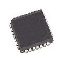
AMIS49587C5871RG ON Semiconductor, AMIS49587C5871RG Datasheet - Page 29

AMIS49587C5871RG
Manufacturer Part Number
AMIS49587C5871RG
Description
IC MODEM PLC 50/60MHZ 28PLCC
Manufacturer
ON Semiconductor
Specifications of AMIS49587C5871RG
Baud Rates
Selectable
Interface
SCI
Voltage - Supply
3 V ~ 3.6 V
Mounting Type
Surface Mount
Package / Case
28-PLCC
Number Of Transmitters
1
Power Supply Requirement
Single
Package Type
PLCC
Operating Temperature Classification
Commercial
Mounting
Surface Mount
Pin Count
28
Operating Temperature (max)
70C
Dual Supply Voltage (typ)
Not RequiredV
Dual Supply Voltage (max)
Not RequiredV
Dual Supply Voltage (min)
Not RequiredV
Lead Free Status / RoHS Status
Lead free / RoHS Compliant
Data Format
-
Lead Free Status / Rohs Status
Compliant
Available stocks
Company
Part Number
Manufacturer
Quantity
Price
Company:
Part Number:
AMIS49587C5871RG
Manufacturer:
ON
Quantity:
3 400
Company:
Part Number:
AMIS49587C5871RG
Manufacturer:
ON Semiconductor
Quantity:
10 000
See Appendix C: SUMMARY of writeconfigNew_request for more details on the data for each mode.
TEST MODE
Description
level of the AMIS−49587 (for CENELEC for example –
never used on the field) and on the reception. Six different
modes are available:
Table 32. GENERAL DESCRIPTION OF WRITECONFIGNEW_REQUEST
FSK +
Alarm Filter
Synchro without Gain Min
Repeater
Time−out−search−initiator
Syntax:
The test mode is used to perform tests on the emission
1. Transmitting 1: the AMIS−49587 transmits the
2. Transmitting 0: the AMIS−49587 transmits the
3. Alternative transmission: the AMIS−49587
4. Reception E0/E1 (= no transmission) : the
5. Reception I0/Q0 (= no transmission) : the
6. Reception I1/Q1 (= no transmission) : the
Base Micro
Initiator
frequency corresponding to the “1” bit value non
stop.
frequency corresponding to the “0” bit value non
stop.
transmits alternatively the frequencies
corresponding to the “1” and “0” bit values.
AMIS−49587 is placed in reception mode (but it is
not able to interpret what it receives) and it sends
on UART the envelop values.
AMIS−49587 is placed in reception mode (but it is
not able to interpret what it receives) and it sends
on UART the channel 0 values of I and Q.
AMIS−49587 is placed in reception mode (but it is
not able to interpret what it receives) and it sends
on UART the channel 1 values of I and Q.
Field
Frame Format:
<STX>
TestMode_Request (DataTx)
Master/Slave/Monitor
Command (arguments)
Length
1 bit (b4)
1 bit (b3)
1 bit (b2)
Length
(b1,b0)
2 bytes
2 bits
<TestMode_Request>
http://onsemi.com
0 to FFFF
Value
00
01
10
11
29
0
1
0
1
x
TESTMODE_REQUEST (Tag 81h)
Description: The TestMode_Request command is used by
the base micro to ask a Transmitting Test to the
AMIS−49587. Then the AMIS−49587 is in Not Set mode
and its data are all initialized.
Remark: This means that the status will indicate that the
AMIS−49587
WriteConfig_Request
without a reset. Be careful with using this mode, since
nothing will indicate that the AMIS−49587 is in this mode.
(transmitting1, transmitting 0, alternative transmission,
E0/E1 reception, I0/Q0 reception, or I1/Q1 reception) (1
byte),
MaxTransmisttingGain(1byte)
Table 33. TESTMODES
Transmitting Fs
Transmitting Fm
Alternative transmission of Fs and Fm
Reception I0/Q0
Reception I1/Q1
Reception E0/E1
The
Disables the improvement of FSK
Enables the improvement of FSK
Enables the alarm filter
Disables the alarm filter
0 disabled
1 enabled
Never Repeater or Mode = Master
Always Repeater
Not Repeater (accept frame ISACall)
Repeater (accept frame ISACall)
In seconds (Not used in Master and Monitor mode)
the frequencies (2 * 2 bytes) and the
field
DataTx
DataTx
is
Mode
Possible Response
not
and
contains
Description
set,
WriteConfigNew_Request
CHK
but
the
it
chosen
won’t
Code
00
01
02
03
04
05
accept
mode


