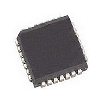
AMIS49587C5871RG ON Semiconductor, AMIS49587C5871RG Datasheet - Page 13

AMIS49587C5871RG
Manufacturer Part Number
AMIS49587C5871RG
Description
IC MODEM PLC 50/60MHZ 28PLCC
Manufacturer
ON Semiconductor
Specifications of AMIS49587C5871RG
Baud Rates
Selectable
Interface
SCI
Voltage - Supply
3 V ~ 3.6 V
Mounting Type
Surface Mount
Package / Case
28-PLCC
Number Of Transmitters
1
Power Supply Requirement
Single
Package Type
PLCC
Operating Temperature Classification
Commercial
Mounting
Surface Mount
Pin Count
28
Operating Temperature (max)
70C
Dual Supply Voltage (typ)
Not RequiredV
Dual Supply Voltage (max)
Not RequiredV
Dual Supply Voltage (min)
Not RequiredV
Lead Free Status / RoHS Status
Lead free / RoHS Compliant
Data Format
-
Lead Free Status / Rohs Status
Compliant
Available stocks
Company
Part Number
Manufacturer
Quantity
Price
Company:
Part Number:
AMIS49587C5871RG
Manufacturer:
ON
Quantity:
3 400
Company:
Part Number:
AMIS49587C5871RG
Manufacturer:
ON Semiconductor
Quantity:
10 000
masked ROM. The RAM contains the necessary space to
store the working data. The back−end interface is done
through the Serial Communication Interface block. This
back−end is used for data transmission with the application
micro controller (containing the application layer for
concentrator, power meter, or other functions) and for the
definition of the modem configuration.
Local Port
actual status of the PLC communication. IO[0] indicates if
Receiving is in progress and is CRC is OK. TX_ENB is an
output port for the information about the transmitter
enabling. TX_DATA is the output for either the transmitting
TRANSMITTER PATH DESCRIPTION (S−FSK
MODULATOR)
of the sine wave frequencies is performed under the control
of the microprocessor. After a signal conditioning step, a
digital to analog conversion is performed. As for the receive
ARM Interface and Control
register, 2 control registers, a flag defining transmit and
receive and 2 16 bit wide frequency step registers defining
f
0) All these registers are memory mapped.
and BYTE_CLK signals when the register TX_RXB in
R_CONF is logic 1. For good operation TX_RXB must
change after an interrupt generated by PRE_BYTE_CLK.
The interface between ARM and transmitter is interrupt
based. At each BYTE_CLK the data from R_TX_DATA is
copied into a buffer register (R_TX_DATA_BUFFER)
M
The controller uses 3 output ports to inform about the
For the generation of the tones, the direct digital synthesis
The interface with the ARM consists in a 8 bit data
The transmitter works synchronous with the BIT_CLK
(mark frequency = data 1) and f
TX_DATA
ALC_IN
TX_OUT
TX_ENB
Transmitter (S− FSK Modulator)
S
(space frequency = data
DETAILED HARDWARE DESCRIPTION
Figure 6. Transmitter Block Diagram
control
Filter
ALC
LP
http://onsemi.com
D/A
13
data (TX_DATA) or a synchronization signal with the
time−slots (PRE_SLOT).
Serial Communication Interface
serial link using a receiving input (RxD) and a transmitting
output (TxD). The input port IO[2] is used to manage the
local communication with the base micro (T_REQ) and the
baud rate can be selected depending on the status of two
local input ports (BR_0, BR_1). These two inputs are taken
in account after a AMIS−49587 reset. Thus when the base
micro wants to change the baud rate, it has to set the two
inputs and then provoke a reset.
path, a sigma delta modulation technique is used. In the
analog domain, the signal is low pass filtered, in order to
remove the high frequency quantization noise, and passed to
the automatic level controller (ACL) block, where the level
of the transmitted signal can be adjusted. The determination
of the signal level is done through the sense circuitry.
address, CRC) is done by the ARM
Sine Wave Generator
DDS. The synthesizer generates in transmission mode a sine
wave either for the space frequency (f
mark frequency (f
generates the sine and cosine waves for the mixing process,
f
quadrature). The space and mark frequencies are defined in
an individual step 16 bit wide register.
SI
The local communication is a half duplex asynchronous
The processing of the physical frame (preamble, MAC
A sine wave is generated with a direct digital synthesizer
, f
& Sine Synthesizer
Transmit Data
SQ
, f
MI
, f
MQ
M
(space and mark signals in phase and
, data1). In reception the synthesizer
Interface
Control
ARM
&
S
, data 0) or for the


