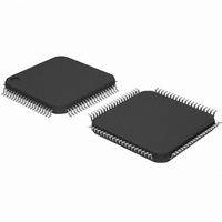
DP83849CVS/NOPB National Semiconductor, DP83849CVS/NOPB Datasheet - Page 38

DP83849CVS/NOPB
Manufacturer Part Number
DP83849CVS/NOPB
Description
IC TXRX ETHERNET PHY DUAL 80TQFP
Manufacturer
National Semiconductor
Type
Transceiverr
Specifications of DP83849CVS/NOPB
Number Of Drivers/receivers
2/2
Protocol
Ethernet
Voltage - Supply
3 V ~ 3.6 V
Mounting Type
Surface Mount
Package / Case
80-TQFP, 80-VQFP
Data Rate
100Mbps
Supply Voltage Range
3V To 3.6V
Logic Case Style
TQFP
No. Of Pins
80
Operating Temperature Range
0°C To +70°C
Msl
MSL 3 - 168 Hours
Filter Terminals
SMD
Rohs Compliant
Yes
Data Rate Max
10Mbps
For Use With
DP83849CVS-EVK - BOARD EVALUATION DP83849CVS
Lead Free Status / RoHS Status
Lead free / RoHS Compliant
Other names
*DP83849CVS
*DP83849CVS/NOPB
DP83849CVS
*DP83849CVS/NOPB
DP83849CVS
Available stocks
Company
Part Number
Manufacturer
Quantity
Price
Company:
Part Number:
DP83849CVS/NOPB
Manufacturer:
NS
Quantity:
618
Company:
Part Number:
DP83849CVS/NOPB
Manufacturer:
Texas Instruments
Quantity:
10 000
www.national.com
5.5 Power Down/Interrupt
The Power Down and Interrupt functions are multiplexed
on pin 18 and pin 44 of the device. By default, this pin func-
tions as a power down input and the interrupt function is
disabled. Setting bit 0 (INT_OE) of MICR (11h) will config-
ure the pin as an active low interrupt output. Ports A and B
can be powered down individually, using the separate
PWRDOWN_INT_A and PWRDOWN_INT_B pins.
5.5.1 Power Down Control Mode
The PWRDOWN_INT pins can be asserted low to put the
device in a Power Down mode. This is equivalent to setting
bit 11 (Power Down) in the Basic Mode Control Register,
BMCR (00h). An external control signal can be used to
drive the pin low, overcoming the weak internal pull-up
resistor. Alternatively, the device can be configured to ini-
tialize into a Power Down state by use of an external pull-
down resistor on the PWRDOWN_INT pin. Since the
device will still respond to management register accesses,
setting the INT_OE bit in the MICR register will disable the
PWRDOWN_INT input, allowing the device to exit the
Power Down state.
5.5.2 Interrupt Mechanisms
Since each port has a separate interrupt pin, the interrupts
can be connected individually or may be combined in a
wired-OR fashion. If the interrupts share a single connec-
tion, each port status should be checked following an inter-
rupt.
The interrupt function is controlled via register access. All
interrupt sources are disabled by default. Setting bit 1
(INTEN) of MICR (11h) will enable interrupts to be output,
dependent on the interrupt mask set in the lower byte of
the MISR (12h). The PWRDOWN_INT pin is asynchro-
nously asserted low when an interrupt condition occurs.
The source of the interrupt can be determined by reading
the upper byte of the MISR. One or more bits in the MISR
will be set, denoting all currently pending interrupts. Read-
ing of the MISR clears ALL pending interrupts.
Example: To generate an interrupt on a change of link sta-
tus or on a change of energy detect power state, the steps
would be:
— Write 0003h to MICR to set INTEN and INT_OE
— Write 0060h to MISR to set ED_INT_EN and
— Monitor PWRDOWN_INT pin
When PWRDOWN_INT pin asserts low, the user would
read the MISR register to see if the ED_INT or LINK_INT
bits are set, i.e. which source caused the interrupt. After
reading the MISR, the interrupt bits should clear and the
PWRDOWN_INT pin will deassert.
LINK_INT_EN
38
5.6 Energy Detect Mode
When Energy Detect is enabled and there is no activity on
the cable, the DP83849C will remain in a low power mode
while monitoring the transmission line. Activity on the line
will cause the DP83849C to go through a normal power up
sequence. Regardless of cable activity, the DP83849C will
occasionally wake up the transmitter to put ED pulses on
the line, but will otherwise draw as little power as possible.
Energy detect functionality is controlled via register Energy
Detect Control (EDCR), address 1Dh.
5.7 Link Diagnostic Capabilities
The DP83849C contains several system diagnostic capa-
bilities for evaluating link quality and detecting potential
cabling faults in Twisted Pair cabling. Software configura-
tion is available through the Link Diagnostics Registers -
Page 2 which can be selected via Page Select Register
(PAGESEL), address 13h. These capabilities include:
— Linked Cable Status
— Link Quality Monitor
— TDR (Time Domain Reflectometry) Cable Diagnostics
5.7.1 Linked Cable Status
In an active connection with a valid link status, the following
diagnostic capabilities are available:
— Polarity reversal
— Cable swap (MDI vs MDIX) detection
— 100Mb Cable Length Estimation
— Frequency offset relative to link partner
— Cable Signal Quality Estimation
5.7.1.1 Polarity Reversal
The DP83849C detects polarity reversal by detecting nega-
tive link pulses. The Polarity indication is available in bit 12
of the PHYSTS (10h) or bit 4 of the 10BTSCR (1Ah).
Inverted polarity indicates the positive and negative con-
ductors in the receive pair are swapped. Since polarity is
corrected by the receiver, this does not necessarily indicate
a functional problem in the cable.
Since the polarity indication is dependent on link pulses
from the link partner, polarity indication is only valid in
10Mb modes of operation, or in 100Mb Auto-Negotiated
mode. Polarity indication is not available in 100Mb forced
mode of operation or in a parallel detected 100Mb mode.
5.7.1.2 Cable Swap Indication
As part of Auto-Negotiation, the DP83849C has the ability
(using Auto-MDIX) to automatically detect a cable with
swapped MDI pairs and select the appropriate pairs for
transmitting and receiving data.
termed MDI, while crossed operation is MDIX. The MDIX
status can be read from bit 14 of the PHYSTS (10h).
Normal operation is


