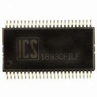
ICS1893CFILF IDT, Integrated Device Technology Inc, ICS1893CFILF Datasheet - Page 81

ICS1893CFILF
Manufacturer Part Number
ICS1893CFILF
Description
PHYCEIVER LOW PWR 3.3V 48-SSOP
Manufacturer
IDT, Integrated Device Technology Inc
Series
PHYceiver™r
Type
PHY Transceiverr
Datasheet
1.ICS1893CFLFT.pdf
(127 pages)
Specifications of ICS1893CFILF
Protocol
MII
Voltage - Supply
3.14 V ~ 3.47 V
Mounting Type
Surface Mount
Package / Case
48-SSOP
Lead Free Status / RoHS Status
Lead free / RoHS Compliant
Number Of Drivers/receivers
-
Other names
1893CFILF
800-1020
800-1020
Available stocks
Company
Part Number
Manufacturer
Quantity
Price
Part Number:
ICS1893CFILFT
Manufacturer:
ICS
Quantity:
20 000
7.14.1 Node Configuration (bit 19.15)
7.14.2 Hardware/Software Priority Status (bit 19.14)
7.14.3 Remote Fault (bit 19.13)
7.14.4 ICS Reserved (bits 19.12:10)
7.14.5 Auto-MDI/MDIX (bits 19. 9:8) (New)
ICS1893CF, Rev. K, 05/13/10
The Node Configuration bit indicates the NOD/MODE.
•
•
The Hardware/Software Priority Status bit indicates the SW mode.
•
•
The ISO/IEC specification defines bit 5.13 as the Remote Fault bit, and bit 19.13 is functionally identical to
bit 5.13. The Remote Fault bit is set based on the Link Control Word received from the remote link partner.
When this bit is a logic:
•
•
See
The ICS1893CF includes the Auto-MDI/MDIX crossover feature. The Auto-MDI/MDIX feature automatically
selects the correct MDI or MDIX configuration to match the cable plant by automatically swapping transmit
and receive signal pairs at the PHY. Auto-MDI/MDIX is defaulted on but may be disabled for test purposes
using either the AMDIX_EN (pin 10) or by writing (bits 19. 9:8). See Table 7-22 for AMDIX_EN (19,9) and
MDI_MODE (19,8) operation.
When AMDIX_EN (bit 19,9) is set to 0, the twisted pair transmit/receive is forced by the MDI_MODE bit
(19,8).
Note:
Table 7-22. AMDIX_EN (Pin 10) and Control Bits 19. 9:8
In Node mode:
The ICS1893CF will only operate in the Node Configuration.
The (MDIO) register bits control the ICS1893CF configuration.
The ICS1893CF will only operate in the Software Configuration.
Zero, it indicates the remote link partner does not detect a Link Fault.
One, it indicates to an STA that the remote link partner detects a Link Fault.
– The SQE Test default setting is enabled.
– The Carrier Sense signal (CRS) is asserted in response to either transmit or receive activity.
Section 7.11.2, “ICS Reserved (bits
AMDIX_EN
ICS1893CF Data Sheet Rev. J - Release
Holding (Pin 10) AMDIX_EN low will also disable the Auto_MDIX function and force pins TP_AP
and TP_AN to be the transmit pair and TP_BP and TP_BN to be the receive pair. AMDIX_EN has
a built in 50K Ohm internal pull-up.
(Pin 10)
x
x
0
Copyright © 2009, Integrated Device Technology, Inc.
AMDIX_EN
[Reg 19:9]
0
0
1
16.14:11)”, the text for which also applies here.
All rights reserved.
81
MDI_MODE
[Reg 19:8]
0
1
x
Chapter 7 Management Register Set
Configuration
Tx/Rx MDI
straight
straight
cross
May, 2010


