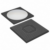
DS31412 Maxim Integrated Products, DS31412 Datasheet - Page 56

DS31412
Manufacturer Part Number
DS31412
Description
IC 12CH DS3/3 FRAMER 349-BGA
Manufacturer
Maxim Integrated Products
Datasheet
1.DS3148.pdf
(89 pages)
Specifications of DS31412
Controller Type
DS3/E3 Framer
Interface
LIU
Voltage - Supply
3.135 V ~ 3.465 V
Current - Supply
960mA
Operating Temperature
-40°C ~ 85°C
Mounting Type
Surface Mount
Package / Case
349-BGA
Lead Free Status / RoHS Status
Lead free / RoHS Compliant
Available stocks
Company
Part Number
Manufacturer
Quantity
Price
Register Name:
Register Description:
Register Address:
Bit #
Name
Default
Bit 0: Transmit CRC Defeat (TCRCD). When this bit is logic 0, the transmit HDLC controller automatically
calculates and appends the 16-bit CRC to the outgoing HDLC message. When this bit is logic 1, the transmit HDLC
controller does not append the CRC to the outgoing message.
Bit 1: Transmit CRC Invert (TCRCI). When this bit is logic 0, the transmit HDLC controller generates the CRC
normally. When this bit is logic 1, the transmit HDLC controller inverts all 16 bits of the generated CRC. This bit is
ignored when CRC generation is disabled (TCRCD = 1). This bit is useful in testing HDLC operation.
Bit 2: Transmit Zero Stuffer Defeat (TZSD). When this bit is logic 0, the transmit HDLC controller performs zero
stuffing on all data between the opening and closing flags of the HDLC message. When this bit is logic 1, the
transmit HDLC controller does not perform zero stuffing.
Bit 3: Transmit Flag/Idle Select (TFS). This control bit determines whether flags or idle bytes are transmitted
between packets.
Bit 4: Transmit Invert Data (TID). When this bit is logic 1, the entire transmit HDLC data stream (including flags
and CRC checksum) is inverted before being transmitted by the DS3/E3 formatter.
Bit 5: Receive Invert Data (RID). When this bit is logic 1, the entire receive HDLC data stream (including flags and
CRC checksum) is inverted before processing by the receive HDLC controller.
Bit 6: Transmit HDLC Reset (THR). A 0-to-1 transition resets the transmit HDLC controller. A reset flushes the
transmit FIFO and causes the transmit HDLC controller to transmit one FEh abort sequence (seven 1s in a row)
followed by continuous transmission of either 7Eh (flags) or FFh (idle) until the beginning of a new packet (at least
two bytes) is written into the transmit HDLC FIFO.
Bit 7: Receive HDLC Reset (RHR). A 0-to-1 transition resets the receive HDLC controller. A reset flushes the
current contents of the receive FIFO and causes the receive HDLC controller to begin searching for a new
incoming HDLC packet.
0 = enable CRC generation (normal operation)
1 = disable CRC generation
0 = do not invert the generated CRC (normal operation)
1 = invert the generated CRC
0 = enable zero stuffing (normal operation)
1 = disable zero stuffing
0 = 7Eh (flags)
1 = FFh (idle)
0 = do not invert transmit HDLC data stream (normal operation)
1 = invert transmit HDLC data stream
0 = do not invert receive HDLC data stream (normal operation)
1 = invert receive HDLC data stream
RHR
7
0
THR
6
0
HCR1
HDLC Control Register 1
50h
RID
5
0
56 of 89
TID
4
0
TFS
3
0
TZSD
2
0
TCRCI
1
0
TCRCD
0
0


