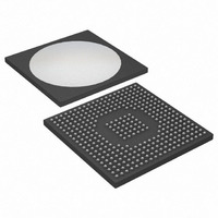
DS31412 Maxim Integrated Products, DS31412 Datasheet - Page 35

DS31412
Manufacturer Part Number
DS31412
Description
IC 12CH DS3/3 FRAMER 349-BGA
Manufacturer
Maxim Integrated Products
Datasheet
1.DS3148.pdf
(89 pages)
Specifications of DS31412
Controller Type
DS3/E3 Framer
Interface
LIU
Voltage - Supply
3.135 V ~ 3.465 V
Current - Supply
960mA
Operating Temperature
-40°C ~ 85°C
Mounting Type
Surface Mount
Package / Case
349-BGA
Lead Free Status / RoHS Status
Lead free / RoHS Compliant
Available stocks
Company
Part Number
Manufacturer
Quantity
Price
Register Name:
Register Description:
Register Address:
Bit #
Name
Default
Bit 0: E3 Code Violation Enable (E3CVE). This bit is ignored in the DS3 mode. In E3 mode, this bit is used to
configure the bipolar violation count register (BPVCR1) to count either bipolar violations (BPV) or code violations
(CV). A BPV is defined as consecutive pulses (or marks) of the same polarity that are not part of an HDB3
codeword. A CV is defined in ITU O.161 as consecutive BPVs of the same polarity.
Bits 1, 2: Frame Error-Counting Control (FECC[1:0])
Bit 3: Error-Counting Control (ECC). This bit is used to control whether the framer increments certain error
counters during OOF conditions. It only affects the error counters that deal with framing overhead:
When this bit is logic 0, these error counters are not allowed to increment during OOF conditions. When this bit is
logic 1, these error counters are allowed to increment during OOF conditions.
Bit 4: Automatic FEBE Defeat (AFEBED). This bit is ignored in E3 mode and in M23 DS3 mode. When this bit is
low, the framer automatically inserts FEBE codes into the transmit data stream by setting all three C bits in M-
subframe 4 to logic 0. A FEBE condition occurs when any received M bits or F bits are in error, or when the
received CP bits indicate a parity error or when the receiver is in the OOF condition.
Bit 5: Transmit FEBE Setting (TFEBE). This bit is only active when AFEBED is logic 1. When this bit is logic 0,
the formatter forces the FEBE code to 111. When this bit is set logic 1, the formatter forces the FEBE code to 000.
Bit 7: Force Receive Framer Resynchronization (FRESYNC). A 0-to-1 transition on this bit causes the receive
framer to resynchronize. This bit must be cleared and set again for a subsequent resynchronization to occur.
FECC[1:0]
00
01
10
11
0 = count BPVs
1 = count CVs
Frame Error-Count Register (FECR1) (when it is configured to count frame errors, not OOFs)
DS3 P-Bit Parity Error-Count Register (PCR1)
DS3 CP-Bit Parity Error-Count Register (CPCR1)
DS3 Far-End Block Error-Count Register (FEBECR1)
0 = do not allow the FECR/PCR/CPCR/FEBECR error counters to increment during OOF
1 = allow the FECR/PCR/CPCR/FEBECR error counters to increment during OOF
0 = automatically insert FEBE codes in the transmit data stream based on detected errors
1 = use the TFEBE control to determine the state of the FEBE codes
0 = force FEBE to 111 (null state)
1 = force FEBE to 000 (active state)
FRESYNC
DS3 Mode: Count OOF occurrences
E3 Mode: Count OOF occurrences
DS3 Mode: Count both F-bit and M-bit errors
E3 Mode: Count bit errors in the FAS word
DS3 Mode: Count only F-bit errors
E3 Mode: Count word errors in the FAS word
DS3 Mode: Count only M-bit errors
E3 Mode: Illegal state
FRAME ERROR-COUNT REGISTER (FECR1) CONFIGURATION
7
0
N/A
—
6
T3E3CR2
DS3/E3 Control Register
11h
TFEBE
5
0
AFEBED
35 of 89
4
0
ECC
3
0
FECC1
2
0
FECC0
1
0
E3CVE
0
0


