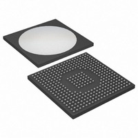
DS31412 Maxim Integrated Products, DS31412 Datasheet - Page 47

DS31412
Manufacturer Part Number
DS31412
Description
IC 12CH DS3/3 FRAMER 349-BGA
Manufacturer
Maxim Integrated Products
Datasheet
1.DS3148.pdf
(89 pages)
Specifications of DS31412
Controller Type
DS3/E3 Framer
Interface
LIU
Voltage - Supply
3.135 V ~ 3.465 V
Current - Supply
960mA
Operating Temperature
-40°C ~ 85°C
Mounting Type
Surface Mount
Package / Case
349-BGA
Lead Free Status / RoHS Status
Lead free / RoHS Compliant
Available stocks
Company
Part Number
Manufacturer
Quantity
Price
Register Name:
Register Description:
Register Address:
Bit #
Name
Default
Bit 0: Load Bit and Error Counts (LC). A low-to-high transition latches the current bit and error counts into the
host-processor-accessible registers BBCR and BBECR and then clears the internal counters. This bit should be
toggled from low to high whenever the host processor wishes to begin a new acquisition period. Must be cleared
and set again for subsequent loads.
Bit 1: Transmit Pattern Load (TC). A low-to-high transition loads the pattern generator. This bit should be toggled
from low to high whenever the host processor loads a new pattern or needs to resynchronize to an existing pattern.
Must be cleared and set again for subsequent loads. For pseudorandom patterns, PS[2:0] must be configured
before toggling TC. For repetitive patterns, PS[2:0], RPL[3:0], and RP[31:0] must be configured before toggling TC.
For alternating word patterns, PS[2:0], AWC[7:0], and RP[31:0] must be configured before toggling TC.
Bit 2: Force Resynchronization (RESYNC). A low-to-high transition forces the receive BERT synchronizer to
resynchronize to the incoming data stream. This bit should be toggled from low to high whenever the host
processor wishes to acquire synchronization on a new pattern. Must be cleared and set again for a subsequent
resynchronization.
Bit 3: Receive Invert Data Enable (RINV)
Bit 4: Transmit Invert Data Enable (TINV)
Bit 5: BERT Enable (BENA). This bit is used to enable the BERT transmitter, replacing the payload, or the entire
DS3/E3 signal (depending on the setting of BM[1:0]). The BERT receiver is always enabled. Configure all BERT
control and pattern registers and toggle the TC control bit before setting BENA.
Bits 6, 7: BERT Mode (BM[1:0]). These bits select whether the BERT pattern replaces only the DS3/E3 payload
or the entire DS3/E3 frame (payload and overhead). These bits also select the BERT transmit direction: line side
(TPOS/TNEG and RPOS/RNEG) or equipment side (TDAT and RDAT).
BM[1:0]
00
01
10
11
0 = do not invert the incoming data stream
1 = invert the incoming data stream
0 = do not invert the outgoing data stream
1 = invert the outgoing data stream
0 = disable BERT transmitter
1 = enable BERT transmitter
Entire frame
Entire frame
BM1
Payload
Payload
7
0
DATA
BM0
6
0
TPOS/TNEG
TPOS/TNEG
TRANSMIT
BCR1
BERT Control Register 1
30h
RDAT
RDAT
BENA
5
0
RPOS/RNEG
RPOS/RNEG
47 of 89
RECEIVE
TINV
TDAT
TDAT
0
4
RINV
3
0
RESYNC
2
0
TC
0
1
LC
0
0


