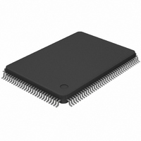
DS21Q42T Maxim Integrated Products, DS21Q42T Datasheet - Page 60

DS21Q42T
Manufacturer Part Number
DS21Q42T
Description
IC FRAMER ENHANCED T1 4X 128TQFP
Manufacturer
Maxim Integrated Products
Datasheet
1.DS21Q42T.pdf
(116 pages)
Specifications of DS21Q42T
Controller Type
T1 Framer
Interface
Parallel/Serial
Voltage - Supply
2.97 V ~ 3.63 V
Current - Supply
75mA
Operating Temperature
0°C ~ 70°C
Mounting Type
Surface Mount
Package / Case
128-TQFP, 128-VQFP
Lead Free Status / RoHS Status
Contains lead / RoHS non-compliant
Available stocks
Company
Part Number
Manufacturer
Quantity
Price
Part Number:
DS21Q42T
Manufacturer:
DALLAS
Quantity:
20 000
Transmit a HDLC Message
1) Make sure HDLC controller is done sending any previous messages and is current sending flags by
2) Enable either the THALF or TNF interrupt.
3) Read THIR to obtain TFULL status.
4) Repeat Step 3.
5) Wait for interrupt, skip to Step 3.
6) Disable THALF or TNF interrupt and enable TMEND interrupt.
7) Wait for an interrupt, then read TUDR status bit to make sure packet was transmitted correctly.
15.
Each Framer/Formatter has the ability to extract/insert data from/ into the Facility Data Link (FDL) in the
ESF framing mode and from/into Fs–bit position in the D4 framing mode. Since SLC–96 utilizes the
Fs-bit position, this capability can also be used in SLC–96 applications. The DS21Q42 contains a
complete HDLC and BOC controller for the FDL and this operation is covered in Section 15.1. To allow
for backward compatibility between the DS21Q42 and earlier devices, the DS21Q42 maintains some
legacy functionality for the FDL and this is covered in Section 15.2. Section 15.3 covers D4 and SLC–96
operation. Please contact the factory for a copy of C language source code for implementing the FDL on
the DS21Q42.
15.1 HDLC and BOC Controller for the FDL
15.1.1 General Overview
The DS21Q42 contains a complete HDLC controller with 64–byte buffers in both the transmit and
receive directions as well as separate dedicated hardware for Bit Oriented Codes (BOC). The HDLC
controller performs all the necessary overhead for generating and receiving Performance Report
Messages (PRM) as described in ANSI T1.403 and the messages as described in AT&T TR54016. The
HDLC controller automatically generates and detects flags, generates and checks the CRC check sum,
generates and detects abort sequences, stuffs and destuffs zeros (for transparency), and byte aligns to the
HDLC data stream. The 64–byte buffers in the HDLC controller are large enough to allow a full PRM to
be received or transmitted without host intervention. The BOC controller will automatically detect
incoming BOC sequences and alert the host. When the BOC ceases, the DS21Q42 will also alert the
host. The user can set the device up to send any of the possible 6–bit BOC codes.
There are thirteen registers that the host will use to operate and control the operation of the HDLC and
BOC controllers. A brief description of the registers is shown in Table 15–1.
checking that the FIFO is empty by reading the TEMPTY status bit in the THIR register.
a. If TFULL = 0, then write a byte into the FIFO and skip to next step (special case occurs when
b. If TFULL = 1, then skip to Step 5.
FDL/Fs EXTRACTION AND INSERTION
the last byte is to be written, in this case set TEOM=1 before writing the byte and then skip to
step 6)
60 of 116


