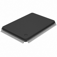
DS21Q42T Maxim Integrated Products, DS21Q42T Datasheet - Page 19

DS21Q42T
Manufacturer Part Number
DS21Q42T
Description
IC FRAMER ENHANCED T1 4X 128TQFP
Manufacturer
Maxim Integrated Products
Datasheet
1.DS21Q42T.pdf
(116 pages)
Specifications of DS21Q42T
Controller Type
T1 Framer
Interface
Parallel/Serial
Voltage - Supply
2.97 V ~ 3.63 V
Current - Supply
75mA
Operating Temperature
0°C ~ 70°C
Mounting Type
Surface Mount
Package / Case
128-TQFP, 128-VQFP
Lead Free Status / RoHS Status
Contains lead / RoHS non-compliant
Available stocks
Company
Part Number
Manufacturer
Quantity
Price
Part Number:
DS21Q42T
Manufacturer:
DALLAS
Quantity:
20 000
DS21Q42
Signal Name: RNEG
Signal Description: Receive Negative Data Input
Signal Type: Input
Sampled on the falling edge of RCLK for data to be clocked through the receive side framer. RPOS and
RNEG can be tied together for an NRZ interface. Connecting RPOS to RNEG disables the bipolar
violation monitoring circuitry.
Signal Name: RCLK
Signal Description: Receive Clock Input
Signal Type: Input
Clock used to clock data through the receive side framer.
PARALLEL CONTROL PORT PINS
Signal Name: INT*
Signal Description: Interrupt
Signal Type: Output
Flags host controller during conditions and change of conditions defined in the Status Registers 1 and 2
and the HDLC Status Register. Active low, open drain output.
Signal Name: FMS
Signal Description: Framer Mode Select
Signal Type: Input
Set low to select DS21Q42 feature set. Set high to select DS21Q41 emulation.
Signal Name: MUX
Signal Description: Bus Operation
Signal Type: Input
Set low to select non–multiplexed bus operation. Set high to select multiplexed bus operation.
Signal Name: D0 to D7/ AD0 to AD7
Signal Description: Data Bus or Address/Data Bus
Signal Type: Input /Output
In non–multiplexed bus operation (MUX = 0), serves as the data bus. In multiplexed bus operation
(MUX = 1), serves as a 8–bit multiplexed address / data bus.
Signal Name: A0 to A5, A7
Signal Description: Address Bus
Signal Type: Input
In non–multiplexed bus operation (MUX = 0), serves as the address bus. In multiplexed bus operation
(MUX = 1), these pins are not used and should be tied low.
Signal Name: ALE(AS)/A6
Signal Description: A6 or Address Latch Enable (Address Strobe)
Signal Type: Input
In non–multiplexed bus operation (MUX = 0), serves as address bit 6. In multiplexed bus operation
(MUX = 1), serves to demultiplex the bus on a positive–going edge.
19 of 116


