COM20022I-HT SMSC, COM20022I-HT Datasheet - Page 49
COM20022I-HT
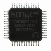
Manufacturer Part Number
COM20022I-HT
Description
IC CTRLR ARCNET 2KX8 RAM 48-TQFP
Manufacturer
SMSC
Series
ARCNETr
Datasheet
1.COM20022I3V-HT.pdf
(82 pages)
Specifications of COM20022I-HT
Controller Type
ARCNET Controller
Interface
Differential
Voltage - Supply
4.5 V ~ 5.5 V
Current - Supply
65mA
Operating Temperature
-40°C ~ 85°C
Mounting Type
Surface Mount
Package / Case
48-TQFP, 48-VQFP
Lead Free Status / RoHS Status
Lead free / RoHS Compliant
Other names
638-1003
Available stocks
Company
Part Number
Manufacturer
Quantity
Price
Company:

Part Number:
COM20022I-HT
Manufacturer:
Standard
Quantity:
5 410
Company:
Part Number:
COM20022I-HT
Manufacturer:
SMSC
Quantity:
455
Company:
Part Number:
COM20022I-HT
Manufacturer:
Microchip Technology
Quantity:
10 000


10 Mbps ARCNET (ANSI 878.1) Controller with 2Kx8 On-Chip RAM
Datasheet
6.6.2
SMSC COM20022I
Transmit Sequence
During a transmit sequence, the microcontroller selects a 256 or 512 byte segment of the RAM buffer and
writes into it. The appropriate buffer size is specified in the "Define Configuration" command. When long
packets are enabled, the COM20022I interprets the packet as either a long or short packet, depending on
whether the buffer address 2 contains a zero or non-zero value. The format of the buffer is shown in
Figure 5.7 Address 0 contains the Source Identifier (SID); Address 1 contains the Destination Identifier
(DID); Address 2 (COUNT) contains, for short packets, the value 256-N, where N represents the number
of information bytes in the message, or for long packets, the value 0, indicating that it is indeed a long
packet. In the latter case, Address 3 (COUNT) would contain the value 512-N, where N represents the
number of information bytes in the message. The SID in Address 0 is used by the receiving node to reply
to the transmitting node. The COM20022I puts the local ID in this location, therefore it is not necessary to
write into this location. Please note that a short packet may contain between 1 and 253 data bytes, while a
long packet may contain between 257 and 508 data bytes. A minimum value of 257 exists on a long
packet so that the COUNT is expressible in eight bits. This leaves three exception packet lengths which
do not fit into either a short or long packet; packet lengths of 254, 255, or 256 bytes. If packets of these
lengths must be sent, the user must add dummy bytes to the packet in order to make the packet fit into a
long packet.
Once the packet is written into the buffer, the microcontroller awaits a logic "1" on the TA bit, indicating that a
previous transmit command has concluded and another may be issued. Each time the message is loaded
and a transmit command issued, it will take a variable amount of time before the message is transmitted,
depending on the traffic on the network and the location of the token at the time the transmit command was
issued. The conclusion of the Transmit Command will generate an interrupt if the Interrupt Mask allows it. If
the device is configured for the Command Chaining operation, please see the Command Chaining section for
further detail on the transmit sequence. Once the TA bit becomes a logic "1", the microcontroller may issue
the "Enable Transmit from Page fnn" command, which resets the TA and TMA bits to logic "0". If the
ADDRESS
COUNT
255
511
0
1
2
Figure 6.3 - RAM Buffer Packet Configuration
N = DATA PACKET LENGTH
SID = SOURCE ID
DID = DESTINATION ID
(DID = 0 FOR BROADCASTS)
SHORT PACKET
COUNT = 256-N
DATA BYTE N-1
DATA BYTE 1
DATA BYTE 2
DATA BYTE N
NOT USED
NOT USED
FORMAT
SID
DID
DATASHEET
Page 49
ADDRESS
COUNT
511
0
1
2
3
COUNT = 512-N
DATA BYTE N-1
LONG PACKET
DATA BYTE N
DATA BYTE 1
DATA BYTE 2
NOT USED
FORMAT
SID
DID
0
Revision 09-27-07
Related parts for COM20022I-HT
Image
Part Number
Description
Manufacturer
Datasheet
Request
R


Part Number:
Description:
FAST ETHERNET PHYSICAL LAYER DEVICE
Manufacturer:
SMSC Corporation
Datasheet:
Part Number:
Description:
357-036-542-201 CARDEDGE 36POS DL .156 BLK LOPRO
Manufacturer:
SMSC Corporation
Datasheet:
Part Number:
Description:
357-036-542-201 CARDEDGE 36POS DL .156 BLK LOPRO
Manufacturer:
SMSC Corporation
Datasheet:
Part Number:
Description:
357-036-542-201 CARDEDGE 36POS DL .156 BLK LOPRO
Manufacturer:
SMSC Corporation
Datasheet:
Part Number:
Description:
4-PORT USB2.0 HUB CONTROLLER
Manufacturer:
SMSC Corporation
Datasheet:
Part Number:
Description:
Manufacturer:
SMSC Corporation
Datasheet:
Part Number:
Description:
Manufacturer:
SMSC Corporation
Datasheet:
Part Number:
Description:
FDC37C672ENHANCED SUPER I/O CONTROLLER WITH FAST IR
Manufacturer:
SMSC Corporation
Datasheet:
Part Number:
Description:
COM90C66LJPARCNET Controller/Transceiver with AT Interface and On-Chip RAM
Manufacturer:
SMSC Corporation
Datasheet:
Part Number:
Description:
Manufacturer:
SMSC Corporation
Datasheet:
Part Number:
Description:
Manufacturer:
SMSC Corporation
Datasheet:
Part Number:
Description:
Manufacturer:
SMSC Corporation
Datasheet:
Part Number:
Description:
Manufacturer:
SMSC Corporation
Datasheet: