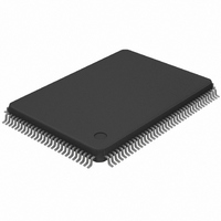
DS21Q43AT Maxim Integrated Products, DS21Q43AT Datasheet - Page 11

DS21Q43AT
Manufacturer Part Number
DS21Q43AT
Description
IC FRAMER E1 QUAD 5V IND 128TQFP
Manufacturer
Maxim Integrated Products
Datasheet
1.DS21Q43AT.pdf
(60 pages)
Specifications of DS21Q43AT
Controller Type
E1 Framer
Interface
Parallel/Serial
Voltage - Supply
4.5 V ~ 5.5 V
Current - Supply
32mA
Operating Temperature
0°C ~ 70°C
Mounting Type
Surface Mount
Package / Case
128-TQFP, 128-VQFP
Dc
0319
Lead Free Status / RoHS Status
Contains lead / RoHS non-compliant
Available stocks
Company
Part Number
Manufacturer
Quantity
Price
Part Number:
DS21Q43AT
Manufacturer:
MAXIM/美信
Quantity:
20 000
Part Number:
DS21Q43AT+
Manufacturer:
MAXIM/美信
Quantity:
20 000
Part Number:
DS21Q43ATN
Manufacturer:
DALLAS
Quantity:
20 000
Data Bus [D0 to D7] or Address/Data Bus [AD0 to AD7]. In non-multiplexed bus operation (MUX=0),
serves as the data bus. In multiplexed bus operation (MUX=1), serves as an 8-bit multiplexed
address/data bus.
Address Bus [A0 to A5]. In non-multiplexed bus operation (MUX=0), serves as the address bus. In
multiplexed bus operation (MUX=1), these pins are not used and should be tied low.
Bus Type Select [BTS]. Strap high to select Motorola bus timing; strap low to select Intel bus timing.
This pin controls the function of the
assume the function listed in parentheses ().
Read Input [
Framer Selects [FS0 and FS1]. Selects which of the four framers to be accessed.
Chip Selects [
A6 or Address Latch Enable [ALE] (Address Strobe [AS]). In non-multiplexed bus operation
(MUX=0), serves as the upper address bit. In multiplexed bus operation (MUX=1), serves to demultiplex
the bus on a positive-going edge.
Write Input [
Positive Supply [V
Signal Ground [V
DS21Q43A FRAMER DECODE Table 1-5
RD
WR
CS
FS1
0
0
1
1
] (Data Strobe [DS]).
]. Must be low to read or write to any of the four framers.
] (Read/Write [R/
SS
DD
]. 0.0 volts.
]. 5.0 volts ± 0.5 volts.
RD
W
]).
(DS), ALE(AS), and
11 of 60
FS0
0
1
0
1
WR
(R/
W
) pins. If BTS=1, then these pins
FRAMER ACCESSED
#0
#1
#2
#3
DS21Q43A


