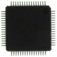
ISP1362BDFA ST-Ericsson Inc, ISP1362BDFA Datasheet - Page 69

ISP1362BDFA
Manufacturer Part Number
ISP1362BDFA
Description
IC USB OTG CONTROLLER 64-LQFP
Manufacturer
ST-Ericsson Inc
Datasheet
1.ISP1362EEUM.pdf
(153 pages)
Specifications of ISP1362BDFA
Controller Type
USB 2.0 Controller
Interface
Parallel/Serial
Voltage - Supply
3 V ~ 3.6 V
Operating Temperature
-40°C ~ 85°C
Mounting Type
Surface Mount
Package / Case
64-LQFP
Lead Free Status / RoHS Status
Lead free / RoHS Compliant
Current - Supply
-
Other names
568-1219
ISP1362BD,151
ISP1362BD-S
ISP1362BD,151
ISP1362BD-S
Available stocks
Company
Part Number
Manufacturer
Quantity
Price
Company:
Part Number:
ISP1362BDFA
Manufacturer:
STE
Quantity:
5
NXP Semiconductors
14. Host Controller registers
Table 34.
ISP1362_5
Product data sheet
Command (Hex)
Read
00
01
02
03
04
05
0D
0E
0F
11
Host Controller registers overview
Write
N/A
81
82
83
84
85
8D
8E
8F
91
Table 33.
The Host Controller contains a set of on-chip control registers. These registers can be
read or written by the Host Controller Driver (HCD). The operational registers are made
compatible to Open Host Controller Interface (OHCI) operational registers. This enables
the OHCI HCD to be easily ported to the ISP1362.
Reserved bits may be defined in future releases of this specification. To ensure
interoperability, the HCD that does not use a reserved field must not assume that the
reserved field contains logic 0. Furthermore, the HCD must always preserve the values of
the reserved field. When a R/W register is modified, the HCD must first read the register,
modify the desired bits and then write the register with the reserved bits still containing the
read value. Alternatively, the HCD can maintain an in-memory copy of previously written
values that can be modified and then written to the Host Controller register. When there is
a write to set or clear the register, bits written to reserved fields must be logic 0.
As shown in
operational registers (32-bit registers) are similar to those defined in the OHCI
specification. The addresses, however, are equal to offset divided by 4.
Register
HcRevision
HcControl
HcCommandStatus
HcInterruptStatus
HcInterruptEnable
HcInterruptDisable
HcFmInterval
HcFmRemaining
HcFmNumber
HcLSThreshold
Bit
31
30 to 24
23 to 0
OtgAltTimer register: bit description
Symbol
START_
TMR
-
CURRENT_
TIME
Table
34, the offset locations (commands to read registers) of these
Rev. 05 — 8 May 2007
Description
This is the start or stop bit of the OTG timer 2. Writing logic 1 will
cause OTG timer 2 to start counting from 0. When the counter reaches
FF FFFFh, this bit is auto-cleared (the counter is stopped). Writing
logic 0 will stop the counting.
If any bit of the OTGInterrupt register is set and the corresponding bit
of the OtgInterruptEnable register is also set, this bit will be
auto-cleared and the current value of the counter will be written to the
CURRENT_TIME field.
0 — stop the timer
1 — start the timer
reserved
When read, these bits give the current value of the timer. The actual
time is CURRENT_TIME
Width
32
32
32
32
32
32
32
32
32
32
Reference
Section 14.1.1 on page 70
Section 14.1.2 on page 70
Section 14.1.3 on page 72
Section 14.1.4 on page 73
Section 14.1.5 on page 74
Section 14.1.6 on page 75
Section 14.2.1 on page 76
Section 14.2.2 on page 77
Section 14.2.3 on page 78
Section 14.2.4 on page 79
0.01 ms.
Single-chip USB OTG Controller
Functionality
HC control and status
registers
HC frame counter
registers
© NXP B.V. 2007. All rights reserved.
ISP1362
68 of 152


