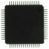
ISP1362BDFA ST-Ericsson Inc, ISP1362BDFA Datasheet - Page 42

ISP1362BDFA
Manufacturer Part Number
ISP1362BDFA
Description
IC USB OTG CONTROLLER 64-LQFP
Manufacturer
ST-Ericsson Inc
Datasheet
1.ISP1362EEUM.pdf
(153 pages)
Specifications of ISP1362BDFA
Controller Type
USB 2.0 Controller
Interface
Parallel/Serial
Voltage - Supply
3 V ~ 3.6 V
Operating Temperature
-40°C ~ 85°C
Mounting Type
Surface Mount
Package / Case
64-LQFP
Lead Free Status / RoHS Status
Lead free / RoHS Compliant
Current - Supply
-
Other names
568-1219
ISP1362BD,151
ISP1362BD-S
ISP1362BD,151
ISP1362BD-S
Available stocks
Company
Part Number
Manufacturer
Quantity
Price
Company:
Part Number:
ISP1362BDFA
Manufacturer:
STE
Quantity:
5
- Current page: 42 of 153
- Download datasheet (703Kb)
NXP Semiconductors
ISP1362_5
Product data sheet
structure in the memory buffer will have an offset of 0 bytes and the second PTD structure
will have an offset of 40 bytes [sum of the block size (32 bytes) and the PTD header size
(8 bytes)]. Because of the fixed block size of the ISP1362 Host Controller, however, even a
PTD with 4 bytes of payload will occupy all the 40 bytes in a block.
In the isochronous PTD, the Host Controller uses a more flexible method to calculate the
PTD offset because each PTD can have a different payload size. The actual amount of
space for the payload, however, must be a multiple of double word. Therefore, a 10 bytes
payload must have a reserved data size of 12 bytes. Take for example there are four PTDs
in the ISTL0 buffer area with payload sizes of 200 bytes, 10 bytes, 1023 bytes and
30 bytes. Then, the offset of each of these PTDs will be as follows:
PTD1 (200 bytes) — offset = 0
PTD2 (10 bytes) — offset = (200 + 8) = 208
PTD3 (1023 bytes) — offset = (200 + 8) + (12 + 8) = 228
PTD4 (30 bytes) — offset = (200 + 8) + (12 + 8) + (1024 + 8) = 1260
The PTD data stored in the Host Controller buffer memory will not be processed, unless
the respective control bits (ATL_Active, INTL_Active, ISTL0_BufferFull or
ISTL1_BufferFull) in HcBufferStatus are set.
The PTD data in the ATL or interrupt buffer memory can be disabled by setting the
respective skip bit in HcATLPTDSkipMap and HcINTLPTDSkipMap. To skip a particular
PTD in the ATL or interrupt buffer, the HCD may set the corresponding bit of the SkipMap
register. For example, setting the HcATLPTDSkipMap register to 0011h will cause the
Host Controller to skip the first and the fifth PTDs in the ATL buffer memory.
Certain fields in the PTD header are used by the Host Controller to inform the HCD about
the status of the transfer. These fields are indicated by the ‘Status Update by HC’ column.
These fields are updated after every transaction to reflect the current status of the PTD.
Fig 22. PTD data stored in the buffer memory
Rev. 05 — 8 May 2007
bottom
top
buffer memory
payload data
payload data
payload data
PTD header
PTD header
PTD header
004aaa121
PTD data #1
PTD data #2
PTD data #N
Single-chip USB OTG Controller
© NXP B.V. 2007. All rights reserved.
ISP1362
41 of 152
Related parts for ISP1362BDFA
Image
Part Number
Description
Manufacturer
Datasheet
Request
R

Part Number:
Description:
IC FILTR/CODEC 14BIT AUD 30TSSOP
Manufacturer:
ST-Ericsson Inc
Datasheet:

Part Number:
Description:
IC FILTR/CODEC 14BIT AUD 30TSSOP
Manufacturer:
ST-Ericsson Inc
Datasheet:

Part Number:
Description:
IC USB HUB CONTROLLER HS 80-LQFP
Manufacturer:
ST-Ericsson Inc
Datasheet:

Part Number:
Description:
IC USB HOST CONTROLLER 128-LQFP
Manufacturer:
ST-Ericsson Inc
Datasheet:

Part Number:
Description:
IC USB PERIPH CONTROLLER 64HVQFN
Manufacturer:
ST-Ericsson Inc
Datasheet:

Part Number:
Description:
IC USB HOST CTRL FULL-SPD 48HVQF
Manufacturer:
ST-Ericsson Inc
Datasheet:

Part Number:
Description:
IC USB CTRL HI-SPEED 64HVQFN
Manufacturer:
ST-Ericsson Inc
Datasheet:

Part Number:
Description:
IC USB CTRL HI-SPEED 64TFBGA
Manufacturer:
ST-Ericsson Inc
Datasheet:

Part Number:
Description:
IC USB CTRL HI-SPEED 64HVQFN
Manufacturer:
ST-Ericsson Inc
Datasheet:

Part Number:
Description:
IC USB CTRL SNGL CHIP 64TFBGA
Manufacturer:
ST-Ericsson Inc
Datasheet:

Part Number:
Description:
IC USB HOST/DEVICE CTRLR 64-LQFP
Manufacturer:
ST-Ericsson Inc
Datasheet:

Part Number:
Description:
IC USB CTRL HI-SPEED 128TFBGA
Manufacturer:
ST-Ericsson Inc
Datasheet:

Part Number:
Description:
IC USB CNTRLR FULL-SPD 48-TSSOP
Manufacturer:
ST-Ericsson Inc
Datasheet:


