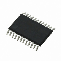
CS4270-DZZ Cirrus Logic Inc, CS4270-DZZ Datasheet - Page 34

CS4270-DZZ
Manufacturer Part Number
CS4270-DZZ
Description
IC CODEC 24BIT 105DB 24TSSOP
Manufacturer
Cirrus Logic Inc
Type
Stereo Audior
Specifications of CS4270-DZZ
Data Interface
Serial
Resolution (bits)
24 b
Number Of Adcs / Dacs
2 / 2
Sigma Delta
Yes
Dynamic Range, Adcs / Dacs (db) Typ
105 / 105
Voltage - Supply, Analog
3.1 V ~ 5.25 V
Voltage - Supply, Digital
3.1 V ~ 5.25 V
Operating Temperature
-40°C ~ 85°C
Mounting Type
Surface Mount
Package / Case
24-TSSOP
Audio Codec Type
Stereo
No. Of Adcs
1
No. Of Dacs
1
No. Of Input Channels
3
No. Of Output Channels
3
Adc / Dac Resolution
24bit
Sampling Rate
216kSPS
Ic Interface Type
I2C
Lead Free Status / RoHS Status
Lead free / RoHS Compliant
For Use With
598-1002 - BOARD EVAL FOR CS4270 CODEC
Lead Free Status / RoHS Status
Lead free / RoHS Compliant, Lead free / RoHS Compliant
Other names
598-1622
Available stocks
Company
Part Number
Manufacturer
Quantity
Price
Company:
Part Number:
CS4270-DZZ
Manufacturer:
CIRRUS
Quantity:
9
Company:
Part Number:
CS4270-DZZ
Manufacturer:
CIRRUS
Quantity:
62
34
8.4
8.4.1
8.4.2
8.4.3
8.4.4
8.4.5
ADC_HPF_
FRZ_A
7
ADC and DAC Control - Address 04h
ADC High Pass Filter Freeze for CH A (Bit 7)
ADC High Pass Filter Freeze for CH B (Bit 6)
Digital Loopback (Bit 5)
DAC Digital Interface Format (Bits 4:3)
ADC Digital Interface Format (Bit 0)
Function:
When this bit is set, the internal high-pass filter DC offset value for channel A are frozen.This value is con-
tinuously subtracted from the conversion result. To recalibrate ADC channel A and obtain a new or con-
tinuous value for the system DC offset, clear this bit. See
Filter” on page
Function:
When this bit is set, the internal high-pass filter for channel B are frozen.The current DC offset value will
be static and continuously subtracted from the conversion. To recalibrate ADC channel A and obtain a
new or continuous value for the system DC offset, clear this bit. See
High-Pass Filter” on page
Function:
When this bit is set, an internal digital loopback from the ADC to the DAC will be enabled. See
5.2.5 “Internal Digital Loopback” on page
Function:
The DAC_Digital_Interface_Format and the options are detailed in
Function:
The required relationship between LRCK, SCLK, and SDOUT for the ADC is defined by the ADC Digital
Interface Format. The options are detailed in
DAC_DIF1 DAC_DIF0
ADC_DIF
0
0
1
1
ADC_HPF_
0
1
FRZ_B
6
23.
Left Justified, up to 24-bit data (default)
0
1
1
0
LOOPBK
DIG_
Left Justified, up to 24-bit data (default)
5
I²S, up to 24-bit data
23.
Table 11. DAC Digital Interface Formats
Table 12. ADC Digital Interface Formats
Description
Right-Justified, 16-bit Data
Right-Justified, 24-bit Data
I²S, up to 24-bit data
DAC_DIF1
Description
4
23.
Table 12
DAC_DIF0
3
and may be seen in
“DC Offset Calibration Using the High-Pass
Format
Reserved
0
1
Table 11
2
Format
“DC Offset Calibration Using the
0
1
2
3
Figures 9
and Figures 9–11.
Reserved
Figure
1
Figure
10
9
and 10.
10
11
11
9
ADC_DIF0
CS4270
DS686F1
0
Section


