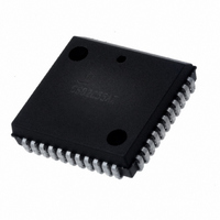
CS80C286-12 Intersil, CS80C286-12 Datasheet - Page 35

CS80C286-12
Manufacturer Part Number
CS80C286-12
Description
IC CPU 16BIT 5V 12.5MHZ 68-PLCC
Manufacturer
Intersil
Datasheet
1.CS80C286-12.pdf
(60 pages)
Specifications of CS80C286-12
Processor Type
80C286 16-Bit
Speed
12.5MHz
Voltage
5V
Mounting Type
Surface Mount
Package / Case
68-PLCC
Lead Free Status / RoHS Status
Contains lead / RoHS non-compliant
Features
-
Available stocks
Company
Part Number
Manufacturer
Quantity
Price
Company:
Part Number:
CS80C286-12
Manufacturer:
INTERSIL
Quantity:
5 510
Part Number:
CS80C286-12
Manufacturer:
HAR
Quantity:
20 000
The processor extension interface uses I/O port addresses
00F8(H), and 00FC(H) which are part of the I/O port address
range reserved by Intersil. An ESC instruction with Machine
Status Word bits EM = 0 and T
operations to one or more of these I/O port addresses inde-
pendent of the value of lOPL and CPL.
ESC instructions with memory references enable the CPU to
accept PEREQ inputs for processor extension operand
transfers. The CPU will determine the operand starting
address and read/write status of the instruction. For each
operand transfer, two or three bus operations are performed,
one word transfer with I/O port address 00FA(H) and one or
two bus operations with memory. Three bus operations are
required for each word operand aligned on an odd byte
address.
Interrupt Acknowledge Sequence
Figure 29 illustrates an interrupt acknowledge sequence per-
formed by the 80C286 in response to an INTR input. An
interrupt acknowledge sequence consists of two INTA bus
operations. The first allows a master 82C59A Programmable
Interrupt Controller (PlC) to determine which if any of its
slaves should return the interrupt vector. An eight bit vector
is read on D
operation to select an interrupt handler routine from the
interrupt table.
0
-D
7
of the 80C286 during the second INTA bus
S
= 0 will perform I/O bus
80C286
35
The Master Cascade Enable (MCE) signal of the 82C288 is
used to enable the cascade address drivers during INTA bus
operations (See Figure 29) onto the local address bus for
distribution to slave interrupt controllers via the system
address bus. The 80C286 emits the LOCK signal (active
LOW) during T
“hold” request will not be honored until the end of the second
INTA bus operation.
Three idle processor clocks are provided by the 80C286
between INTA bus operations to allow for the minimum INTA
to INTA time and CAS (cascade address) out delay of the
82C59A. The second INTA bus operation must always have
at least one extra T
READY. A
state of the second INTA bus operation. This prevents bus
contention between the cascade address drivers and CPU
address drivers. The extra T
80C286 to resume driving the address lines for subsequent
bus operations.
23
-A
S
0
are in three-state OFF until after the first T
of the first INTA bus operation. A local bus
C
state added via logic controlling
C
state allows time for the
C


