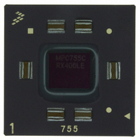
MPC755CRX400LE Freescale Semiconductor, MPC755CRX400LE Datasheet - Page 15

MPC755CRX400LE
Manufacturer Part Number
MPC755CRX400LE
Description
IC MPU 32BIT 400MHZ PPC 360-CBGA
Manufacturer
Freescale Semiconductor
Datasheet
1.MPC755BPX300LE.pdf
(56 pages)
Specifications of MPC755CRX400LE
Processor Type
MPC7xx PowerPC 32-Bit
Speed
400MHz
Voltage
2V
Mounting Type
Surface Mount
Package / Case
360-FCCBGA
Family Name
MPC7xx
Device Core
PowerPC
Device Core Size
64b
Frequency (max)
400MHz
Instruction Set Architecture
RISC
Supply Voltage 1 (typ)
2V
Operating Supply Voltage (max)
2.1V
Operating Supply Voltage (min)
1.9V
Operating Temp Range
0C to 105C
Operating Temperature Classification
Commercial
Mounting
Surface Mount
Pin Count
360
Package Type
FCCBGA
Lead Free Status / RoHS Status
Contains lead / RoHS non-compliant
Features
-
Lead Free Status / Rohs Status
Not Compliant
Available stocks
Company
Part Number
Manufacturer
Quantity
Price
Company:
Part Number:
MPC755CRX400LE
Manufacturer:
MOT
Quantity:
12 388
Company:
Part Number:
MPC755CRX400LE
Manufacturer:
Freescale Semiconductor
Quantity:
10 000
Freescale Semiconductor
At recommended operating conditions (see
Setup times: All inputs
Input hold times: TLBISYNC, MCP, SMI
Input hold times: All inputs, except TLBISYNC, MCP, SMI
Valid times: All outputs
Output hold times: All outputs
SYSCLK to output enable
SYSCLK to output high impedance (all except ABB, ARTRY, DBB)
SYSCLK to ABB, DBB high impedance after precharge
Maximum delay to ARTRY precharge
SYSCLK to ARTRY high impedance after precharge
Notes:
1. Revisions prior to Rev. 2.8 (Rev. E) were limited in performance and did not conform to this specification. For more
2. Guaranteed by design and characterization.
3. t
4. Per the 60x bus protocol, TS, ABB, and DBB are driven only by the currently active bus master. They are asserted low, then
5. Per the 60x bus protocol, ARTRY can be driven by multiple bus masters through the clock period immediately following AACK.
6. MCP and SRESET must be held asserted for a minimum of two bus clock cycles; INT and SMI should be held asserted until
information, refer to
SYSCLK to compute the actual time duration (in ns) of the parameter in question.
precharged high before returning to high-Z as shown in
0.5 × t
following clock will not contend with the precharge. Output valid and output hold timing is tested for the signal asserted.
Output valid time is tested for precharge. The high-Z behavior is guaranteed by design.
Bus contention is not an issue since any master asserting ARTRY will be driving it low. Any master asserting it low in the first
clock following AACK will then go to high-Z for one clock before precharging it high during the second cycle after the assertion
of AACK. The nominal precharge width for ARTRY is 1.0 t
first opportunity for another master to assert ARTRY. Output valid and output hold timing is tested for the signal asserted.
Output valid time is tested for precharge. The high-Z and precharge behavior is guaranteed by design.
the exception is taken; CKSTP_IN must be held asserted until the system has been reset. See the MPC750 RISC
Microprocessor Family User’s Manual for more information.
sysclk
is the period of the external clock (SYSCLK) in ns. The numbers given in the table must be multiplied by the period of
sysclk
, that is, less than the minimum t
Section 10.2, “Part Numbers Not Fully Addressed by This Document.”
MPC755 RISC Microprocessor Hardware Specifications, Rev. 8
Table 10. Processor Bus AC Timing Specifications
Parameter
Table
3)
sysclk
period, to ensure that another master asserting TS, ABB, or DBB on the
Figure
sysclk
; that is, it should be high-Z as shown in
6. The nominal precharge width for TS, ABB, or DBB is
Symbol
t
t
t
KHABPZ
KHARPZ
t
t
t
t
KHARP
t
t
t
KHOE
KHOV
KHOX
KHOZ
IVKH
IXKH
IXKH
All Speed Grades
Electrical and Thermal Characteristics
Min
2.5
0.6
0.2
1.0
0.5
—
—
—
—
—
1
Max
4.1
6.0
1.0
—
—
—
—
—
1
2
Figure 6
t
t
t
Unit
sysclk
sysclk
sysclk
ns
ns
ns
ns
ns
ns
ns
before the
Notes
2, 3, 4
2, 3, 5
2, 3, 5
6
6
2
2
15


