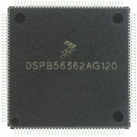
DSPB56362AG120 Freescale Semiconductor, DSPB56362AG120 Datasheet - Page 44

DSPB56362AG120
Manufacturer Part Number
DSPB56362AG120
Description
IC DSP 24BIT AUD 120MHZ 144-LQFP
Manufacturer
Freescale Semiconductor
Series
Symphony™r
Type
Audio Processorr
Datasheet
1.DSPB56362AG120.pdf
(152 pages)
Specifications of DSPB56362AG120
Interface
Host Interface, I²C, SAI, SPI
Clock Rate
120MHz
Non-volatile Memory
ROM (126 kB)
On-chip Ram
42kB
Voltage - I/o
3.30V
Voltage - Core
3.30V
Operating Temperature
-40°C ~ 85°C
Mounting Type
Surface Mount
Package / Case
144-LQFP
Device Core Size
24b
Architecture
Modified Harvard
Format
Fixed Point
Clock Freq (max)
120MHz
Mips
120
Device Input Clock Speed
120MHz
Ram Size
42KB
Program Memory Size
90KB
Operating Supply Voltage (typ)
3.3V
Operating Supply Voltage (min)
3.14V
Operating Supply Voltage (max)
3.46V
Operating Temp Range
-40C to 105C
Operating Temperature Classification
Industrial
Mounting
Surface Mount
Pin Count
144
Package Type
LQFP
Product
DSPs
Data Bus Width
24 bit
Processor Series
DSP563xx
Core
56000
Numeric And Arithmetic Format
Fixed-Point
Instruction Set Architecture
Modified Harvard
Device Million Instructions Per Second
120 MIPS
Maximum Clock Frequency
120 MHz
Program Memory Type
Flash
Data Ram Size
42 KB
Operating Supply Voltage
3.3 V
Maximum Operating Temperature
+ 105 C
Mounting Style
SMD/SMT
Interface Type
SPI, I2C, ESAI, SHI
Minimum Operating Temperature
- 40 C
Lead Free Status / RoHS Status
Lead free / RoHS Compliant
Available stocks
Company
Part Number
Manufacturer
Quantity
Price
Company:
Part Number:
DSPB56362AG120
Manufacturer:
FSC
Quantity:
12 000
Company:
Part Number:
DSPB56362AG120
Manufacturer:
FREESCA
Quantity:
273
Company:
Part Number:
DSPB56362AG120
Manufacturer:
Freescale Semiconductor
Quantity:
10 000
Part Number:
DSPB56362AG120
Manufacturer:
N/A
Quantity:
20 000
External Memory Expansion Port (Port A)
3.10.2
The selection guides provided in
Final selection should be based on the timing provided in the following tables. As an example, the selection
guide suggests that 4 wait states must be used for 100 MHz operation when using Page Mode DRAM.
However, by using the information in the appropriate table, a designer may choose to evaluate whether
fewer wait states might be used by determining which timing prevents operation at 100 MHz, running the
chip at a slightly lower frequency (e.g., 95 MHz), using faster DRAM (if it becomes available), and control
factors such as capacitive and resistive load to improve overall system performance.
3-18
AA0–AA3
D0–D23
A0–A17
DRAM Timing
WR
RD
TA
Figure 3-13
114
Figure 3-12 SRAM Write Access
101
DSP56362 Technical Data, Rev. 4
112
and
107
Figure 3-16
100
110
102
108
should be used for primary selection only.
119
109
Data
Out
103
111
118
Freescale Semiconductor
AA0469


