HI7188IN Intersil, HI7188IN Datasheet - Page 17
HI7188IN
Manufacturer Part Number
HI7188IN
Description
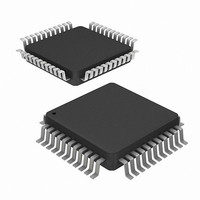
CONV A/D 16BIT 8:1 MUX 44-MQFP
Manufacturer
Intersil
Datasheet
1.HI7188IN.pdf
(24 pages)
Specifications of HI7188IN
Number Of Bits
16
Sampling Rate (per Second)
240
Data Interface
QSPI™, Serial, SPI™
Number Of Converters
1
Power Dissipation (max)
50mW
Voltage Supply Source
Analog and Digital, Dual ±
Operating Temperature
-40°C ~ 85°C
Mounting Type
Surface Mount
Package / Case
44-QFP
Lead Free Status / RoHS Status
Contains lead / RoHS non-compliant
Available stocks
Company
Part Number
Manufacturer
Quantity
Price


RAM0 and RAM1. The RAMs are configured such that when
one is internally writable the other is readable via serial I/O.
The following paragraphs describe the data RAM operation.
Please refer to the Functional Block Diagram.
For example, from initialization, RAM0 is writable, RAM1 is
readable, EOS is inactive. Conversion completes on all
active logical channels (RAM0 stores conversion N data)
and the EOS interrupt is generated. Internally, the
microsequencer switches RAM0 to readable, RAM1 to
writable. The user can read the data RAM to obtain N
conversion results, clearing the EOS interrupt.
The next conversion N+1 completes on all active logical
channels (RAM1 stores N+1 data). If a data RAM (RAM0
containing N data) read has been completed before the N+1
conversion scan has completed, RAM1 will switch to being
readable and RAM0 is writable. This is normal operation and
no conversion results are lost.
If the data RAM (RAM0 containing N data) is not completely
read before the N+1 conversion is completed, there are two
possible results.
Clocking/Oscillators
The master clock of the HI7188 can be supplied by either a
crystal connected between the OSC
shown in Figure 13A or a CMOS compatible clock signal
connected to the OSC
floating the OSC
internal clock generator to derive the clock edges required
for both analog and digital sections. The HI7188 is designed
or a 3.6864MHz clock to maintain Line Noise Rejection.
Crystal Operation
Using a crystal to generate the clock, care must be taken to
minimize any external stray capacitance/inductance seen by
the OSC
(crystal) loop noise will result in a non reliable master clock,
which in turn, will produce erroneous conversion results. The
crystal should be connected as close to the HI7188 device
as physically possible. If you cannot meet these
requirements, we would recommend you use an External
CMOS Clock instead of the crystal.
1. The data RAM read has not been started (RAM0 containing
2. The data RAM (RAM0 containing N data) read has been
N data), EOS remains active low and the microsequencer
will switch RAM1 to be readable and RAM0 to be writable.
This has the effect of overwriting conversion N with N+2.
started but is not complete, the read pointer remains with
RAM0 and the write pointer remains with RAM1. This has
the effect of overwriting conversion N+1 with N+2 before
N+1 can be read, therefore conversion N+1 is lost.
1
and OSC
2
pin. The master clock is used by the
2
pins. If care is not taken, the feedback
1
pin as shown in Figure 13B and
17
1
and OSC
2
pins as
HI7188
External CMOS Clock Operation
When driving the HI7188 with an external CMOS clock, the
clock should never be turned off. If the clock is turned off, the
device should be re-synchronized by resetting either
manually via the RESET pin or by the following special
software instructions. If the device is not re-synchronized
erroneous conversion results may be observed. The
hardware reset will clear all registers and RAMs as defined
in the data sheet. The software reset is achieved by either
performing an I/O access of any calibration RAM or cycling
the device through a sleep cycle.
Calibration RAM Access
To re-synchronize the conversion process the user may
perform an I/O access of any calibration RAM (read or write).
When the user performs this I/O access the microsequencer
stops the conversion process, resets the modulator, digital
filter and waits until the I/O is complete. After the I/O is
completed the microsequencer automatically restarts the
conversion process.
Sleep Cycle
Another method to re-synchronize the conversion process is
to cycle the device through a sleep cycle. The user places
the device in SLEEP mode by writing the SLP bit (CR<3>) of
the Control Register to logic one. The microsequencer will
stop the conversion process, reset the conversion pointer to
logical channel one, clear the four line noise rejection filters
and deactivate EOS. The serial interface, calibration/data
RAMs, CR and CCR are not affected.
To return from sleep mode the user changes the SLP bit
from high to low. This restarts the conversion process
beginning with logical channel 1. If line noise rejection (LNR)
is enabled, it takes four complete scans (all eight channels)
to refill the four line noise rejection filters before an EOS
interrupt. If LNR is not enabled, it takes one conversion scan
of only the active channels before an EOS interrupt.
Recalibration is not required since the calibration RAMs are
not effected by the sleep operation.
FIGURE 13B. EXTERNAL CMOS CLOCK OPERATION
X-3.6864MHz
FIGURE 13A. CRYSTAL OPERATION
OSC
5
1
X-3.6864MHz
HI7188
OSC
5
1
OSC
HI7188
6
2
CONNECTED
OSC
NOT
6
2
Related parts for HI7188IN
Image
Part Number
Description
Manufacturer
Datasheet
Request
R

Part Number:
Description:
8-channel, 16-bit, High Precision, Sigma-delta A/d Sub-system
Manufacturer:
Intersil Corporation
Datasheet:
Part Number:
Description:
Intersil Corporation [CMOS Serial Controller Interface]
Manufacturer:
Intersil Corporation
Datasheet:
Part Number:
Description:
Manufacturer:
Intersil Corporation
Datasheet:
Part Number:
Description:
357-036-542-201 CARDEDGE 36POS DL .156 BLK LOPRO
Manufacturer:
Intersil Corporation
Datasheet:
Part Number:
Description:
1024-Word x 4-Bit LSI Static RAM
Manufacturer:
Intersil Corporation
Datasheet:
Part Number:
Description:
General Purpose NPN Transistor Arrays FN341.4
Manufacturer:
Intersil Corporation
Datasheet:
Part Number:
Description:
CMOS 16-Bit Microprocessor
Manufacturer:
Intersil Corporation
Datasheet:
Part Number:
Description:
Manufacturer:
Intersil Corporation
Datasheet:
Part Number:
Description:
Manufacturer:
Intersil Corporation
Datasheet:
Part Number:
Description:
Manufacturer:
Intersil Corporation
Datasheet:
Part Number:
Description:
Manufacturer:
Intersil Corporation
Datasheet:
Part Number:
Description:
CMOS 6-Bit Latch and Decoder Memory Interfaces
Manufacturer:
Intersil Corporation
Datasheet:
Part Number:
Description:
CA3046General Purpose NPN Transistor Arrays
Manufacturer:
Intersil Corporation
Datasheet:
Part Number:
Description:
Manufacturer:
Intersil Corporation
Datasheet:
Part Number:
Description:
TR909 DLC/FLC SLIC with Low Power Standby
Manufacturer:
Intersil Corporation
Datasheet: