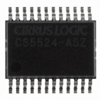
CS5524-ASZ Cirrus Logic Inc, CS5524-ASZ Datasheet - Page 35

CS5524-ASZ
Manufacturer Part Number
CS5524-ASZ
Description
IC ADC 24BIT 4CH 20SSOP
Manufacturer
Cirrus Logic Inc
Specifications of CS5524-ASZ
Number Of Converters
1
Package / Case
24-SSOP
Number Of Bits
24
Data Interface
Serial
Power Dissipation (max)
14.8mW
Voltage Supply Source
Analog and Digital
Operating Temperature
-40°C ~ 85°C
Mounting Type
Surface Mount
Number Of Adc Inputs
4
Architecture
Delta-Sigma
Conversion Rate
617 SPs
Resolution
24 bit
Input Type
Voltage
Interface Type
Serial (3-Wire)
Voltage Reference
2.5 V
Supply Voltage (max)
5 V
Supply Voltage (min)
25 mV
Maximum Power Dissipation
500 mW
Maximum Operating Temperature
+ 85 C
Mounting Style
SMD/SMT
Input Voltage
25 mV to 5 V
Minimum Operating Temperature
- 40 C
Lead Free Status / RoHS Status
Lead free / RoHS Compliant
For Use With
598-1012 - EVAL BOARD FOR CS5524 ADC
Lead Free Status / Rohs Status
Lead free / RoHS Compliant
Other names
598-1106-5
Available stocks
Company
Part Number
Manufacturer
Quantity
Price
Part Number:
CS5524-ASZ
Manufacturer:
CIRRUS
Quantity:
20 000
conversion words deep. Further note that the type
of conversion(s) performed and the way to access
the resulting data from the FIFO is determined by
the MC (multiple conversion), the LP (loop), the
RC (read convert), and the DP (depth pointer) bits
in the configuration register.
2.4.1 Conversion Protocol
The CS552x offer six different conversion modes,
which can be categorized into two main types of
conversions: one-Setup conversions, which refer-
ence only one Setup, and multiple-Setup conver-
sions, which reference any number of Setups. The
converter can be instructed to perform single con-
versions or repeated conversions (with or without
wait) in either of these modes, using the MC, LP,
and RC bits in the Configuration Register. The MC
bit controls whether the part will do one-Setup or
multiple-Setup conversions. The LP bit controls
whether the part will perform a single or repeated
conversion set. When doing repeated conversion
sets, the RC bit controls whether or not the convert-
er will wait for the data from the current conversion
set to be read before beginning the next conversion
set. The sections that follow further detail the vari-
ous conversion modes.
2.4.1.1 Single, One-Setup Conversion
(LP = 0 MC = 0 RC = X)
In this conversion mode, the ADC will perform a
single conversion, referencing only one Setup, and
return to command mode after the data word has
been fully read. The 8-bit command word contains
the CSRP bits, which instruct the converter which
Setup to use when performing the conversion.
To perform a single, one-Setup conversion, the MC
and LP bits in the Configuration Register must be
set to '0'. Then, the 8-bit command word that refer-
ences the desired Setup must be sent to the convert-
er. The ADC will then perform a single conversion
on the referenced Setup, and SDO will fall to indi-
cate that the conversion is complete. Thirty-two
DS317F4
SCLKs are then needed to read the conversion
word from the data register. The first 8 SCLKs are
used to clear the SDO flag. During the last 24
SCLKs, the data word will be output from the con-
verter on the SDO line. The part returns to com-
mand mode immediately after the data word has
been read, where it waits for the next command to
be issued.
2.4.1.2 Repeated One-Setup Conversions with-
out Wait
(LP = 1 MC = 0 RC = 0)
In this conversion mode, the ADC will repeatedly
perform conversions, referencing only one Setup.
The 8-bit command word contains the CSRP bits,
which instruct the converter which Setup to use
when performing the conversion. Note that in this
mode, the part will continually perform conver-
sions, and the user need not read every conversion
as it becomes available. Although conversions can
be read whenever they are needed, they must be
read within one conversion cycle (defined by the
referenced Setup), as the data word will be over-
written when new conversion data becomes avail-
able. The SDO line rises and falls to indicate the
availability of new conversion data. When new
data is available, the current conversion data will
be lost, or in the case that the user has only read a
part of the conversion word, the remainder of the
conversion word will be corrupted.
To perform repeated, one-Setup conversions with
no wait, the MC bit must be set to '0', the LP bit
must be set to '1', and the RC bit must be set to '0'
in the Configuration Register. Then, the 8-bit com-
mand word that references the desired Setup must
be sent to the converter. The ADC will then begin
performing conversions on the referenced Setup,
and SDO will fall to indicate when a conversion is
complete, and data is available. Thirty-two SCLKs
are then needed to read the conversion word from
the data register. The first 8 SCLKs are used to
clear the SDO flag. During the last 24 SCLKs, the
data word will be output from the converter on the
CS5521/22/23/24/28
35


