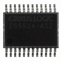
CS5524-ASZ Cirrus Logic Inc, CS5524-ASZ Datasheet - Page 3

CS5524-ASZ
Manufacturer Part Number
CS5524-ASZ
Description
IC ADC 24BIT 4CH 20SSOP
Manufacturer
Cirrus Logic Inc
Specifications of CS5524-ASZ
Number Of Converters
1
Package / Case
24-SSOP
Number Of Bits
24
Data Interface
Serial
Power Dissipation (max)
14.8mW
Voltage Supply Source
Analog and Digital
Operating Temperature
-40°C ~ 85°C
Mounting Type
Surface Mount
Number Of Adc Inputs
4
Architecture
Delta-Sigma
Conversion Rate
617 SPs
Resolution
24 bit
Input Type
Voltage
Interface Type
Serial (3-Wire)
Voltage Reference
2.5 V
Supply Voltage (max)
5 V
Supply Voltage (min)
25 mV
Maximum Power Dissipation
500 mW
Maximum Operating Temperature
+ 85 C
Mounting Style
SMD/SMT
Input Voltage
25 mV to 5 V
Minimum Operating Temperature
- 40 C
Lead Free Status / RoHS Status
Lead free / RoHS Compliant
For Use With
598-1012 - EVAL BOARD FOR CS5524 ADC
Lead Free Status / Rohs Status
Lead free / RoHS Compliant
Other names
598-1106-5
Available stocks
Company
Part Number
Manufacturer
Quantity
Price
Part Number:
CS5524-ASZ
Manufacturer:
CIRRUS
Quantity:
20 000
DS317F4
3. PIN DESCRIPTIONS .............................................................................................................. 48
4. SPECIFICATION DEFINITIONS ............................................................................................. 51
5. ORDERING INFORMATION .................................................................................................. 52
6. ENVIRONMENTAL, MANUFACTURING, & HANDLING INFORMATION ............................ 52
7. PACKAGE DIMENSION DRAWINGS ................................................................................... 53
2.3 Calibration ....................................................................................................................... 31
2.4 Performing Conversions and Reading the Data Conversion FIFO .................................. 34
2.5 Conversion Output Coding .............................................................................................. 40
2.6 Digital Filter ..................................................................................................................... 42
2.7 Clock Generator .............................................................................................................. 42
2.8 Power Supply Arrangements ........................................................................................... 43
2.9 Digital Gain Scaling ........................................................................................................ 45
2.10 Getting Started .............................................................................................................. 46
2.11 PCB Layout ................................................................................................................... 47
3.1 Clock Generator .............................................................................................................. 49
3.2 Control Pins and Serial Data I/O ..................................................................................... 49
3.3 Measurement and Reference Inputs ............................................................................... 49
3.4 Power Supply Connections ............................................................................................. 50
2.2.8 Configuration Register ........................................................................................ 28
2.3.1 Self Calibration .................................................................................................... 31
2.3.2 System Calibration .............................................................................................. 32
2.3.3 Calibration Tips ................................................................................................... 34
2.3.4 Limitations in Calibration Range ......................................................................... 34
2.4.1 Conversion Protocol ............................................................................................ 35
2.4.2 Calibration Protocol ............................................................................................. 38
2.4.3 Example of Using the CSRs to Perform Conversions and Calibrations .............. 38
2.5.1 Conversion Data FIFO Descriptions ................................................................... 41
2.8.1 Charge Pump Drive Circuits ............................................................................... 45
2.2.7.5 Unipolar/Bipolar Bit ............................................................................. 28
2.2.8.1 Chop Frequency Select ...................................................................... 28
2.2.8.2 Conversion/Calibration Control Bits .................................................... 28
2.2.8.3 Power Consumption Control Bits ........................................................ 28
2.2.8.4 Charge Pump Disable ......................................................................... 29
2.2.8.5 Reset System Control Bits .................................................................. 29
2.2.8.6 Data Conversion Error Flags .............................................................. 29
2.4.1.1 Single, One-Setup Conversion ........................................................... 35
2.4.1.2 Repeated One-Setup Conversions without Wait ................................ 35
2.4.1.3 Repeated One-Setup Conversions with Wait ..................................... 36
2.4.1.4 Single, Multiple-Setup Conversions .................................................... 36
2.4.1.5 Repeated Multiple-Setup Conversions without Wait ........................... 37
2.4.1.6 Repeated Multiple-Setup Conversions with Wait ................................ 37
CS5521/22/23/24/28
3


