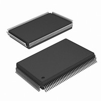
ISL51002CQZ-150 Intersil, ISL51002CQZ-150 Datasheet - Page 24

ISL51002CQZ-150
Manufacturer Part Number
ISL51002CQZ-150
Description
IC FRONT END 10BIT VID 128-MQFP
Manufacturer
Intersil
Datasheet
1.ISL51002CQZ-165.pdf
(32 pages)
Specifications of ISL51002CQZ-150
Number Of Bits
10
Number Of Channels
3
Power (watts)
1.2W
Voltage - Supply, Analog
1.8V, 3.3V
Voltage - Supply, Digital
1.8V, 3.3V
Package / Case
128-MQFP, 128-PQFP
Lead Free Status / RoHS Status
Lead free / RoHS Compliant
Available stocks
Company
Part Number
Manufacturer
Quantity
Price
Company:
Part Number:
ISL51002CQZ-150
Manufacturer:
Intersil
Quantity:
500
SOG
For component YPbPr signals, the sync signal is embedded
on the Y-Channel’s video, which is connected to the green
input, hence the name SOG (Sync on Green). The horizontal
sync information is encoded onto the video input by adding
the sync tip during the blanking interval. The sync tip level is
typically 0.3V below the video black level.
To minimize the loading on the green channel, the SOG input
for each of the green channels should be AC-coupled to the
ISL51002 through a series combination of a 10nF capacitor
and a 500Ω resistor.
SOG Slicer
The SOG input has programmable threshold, 40mV of
hysteresis, and an optional low pass filter than can be used
to remove high frequency video spikes (generated by
overzealous video peaking in a DVD player, for example)
that can cause false SOG triggers. The SOG threshold sets
the comparator threshold relative to the sync tip (the bottom
of the SOG pulse).
Inside the ISL51002, a 1µA pulldown ensures that each sync
tip triggersthe clamp circuit causing the tip to be clamped to a
600mV level. A comparator compares the SOG signal with an
internal 4-bit programmable threshold level reference ranging
from 0mV to 300mV above the sync clamp level. The SOG
threshold level, hysteresis, and low-pass filter is programmed
via registers 0x30and 0x31. If the Sync-On-Green function is
not needed, the SOG
SYNC Processing
The ISL51002 can process sync signals from 3 different
sources: discrete HSYNC and VSYNC, composite sync on
the HSYNC input, or composite sync from a Sync-On-Green
(SOG) signal embedded on the Green video input. The
ISL51002 has SYNC activity detect functions to help the
firmware determine which sync source is available.
R(GB)
R(GB)
R(GB)
R(GB)
R(GB)
R(GB)
R(GB)
R(GB)
GND
GND
GND
GND
IN
IN
IN
IN
2
2
3
3
0
0
1
1
DC RESTORE
(Figure 2)
CLAMP DAC
VGA0
VGA1
VGA2
VGA3
IN
DC RESTORATION
pin(s) may be left unconnected.
V
V
IN
V
IN
+
CLAMP
-
24
GENERATION
PGA
CLAMP
FIGURE 1. VIDEO FLOW (INCLUDING ABLC™)
INPUT
BANDWIDTH
BANDWIDTH
CONTROL
BLOCK
ABLC
TO
ISL51002
OFFSET
DAC
Macrovision
The ISL51002 automatically detects the presense of
Macrovision-encoded video. When Macrovision is detected,
it generates a mask signal that is ANDed with the incoming
SOG CSYNC signal to remove the Macrovision before the
HSYNC goes to the PLL. No additional programming is
required to support Macrovision.
The mask signal is also applied to the HSYNC
When Sync Mask Disable = 0, any Macrovision present on
the incoming sync will not be visible on HSYNC
application requires the Macrovision pulses to be visible on
HSYNC
0x7A-bit 4).
Headswitching from Analog Videotape Signals
Occasionally this AFE may be used to digitize signals
coming from analog videotape sources. The most common
example of this is a Digital VCR (which for best signal quality
would be connected to this AFE with a component YPbPr
connection). If the digital VCR is playing an older analog
VHS tape, the sync signals from the VCR may contain the
worst of the traditional analog tape artifacts: headswitching.
Headswitching is traditionally the enemy of PLLs with large
capture ranges, because a headswitch can cause the
HSYNC period to change by as much as ±90%. To the PLL,
this can look like a frequency change of -50% to +900%,
causing errors in the output frequency (and obviously the
phase) to change. Subsequent HSYNCs have the correct,
original period, but most analog PLLs will take dozens of
lines to settle back to the correct frequency and phase after
a headswitch disturbance. This causes the top of the image
to “tear” during normal playback. In “trick modes” (fast
forward and rewind), the HSYNC signal has multiple
headswitch-like discontinuities, and many PLLs never settle
to the correct value before the next headswitch, rendering
the image completely unintelligible.
10
OUT
10-BIT ADC
OFFSET
ABLC™
FIXED
COMPENSATION (ABLC™) LOOP
, set the HSYNC
AUTOMATIC BLACK LEVEL
10
10
ABLC™
10
OUT
REGISTERS
ABLC™
CONTROL
10
OFFSET
Mask Disable bit (register
10
OFFSET
FIXED
10
0X000
10
FORMATTER
OUT
September 19, 2007
TO OUTPUT
OUT
signal.
. If the
FN6164.2


