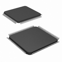
LM9830VJD/NOPB National Semiconductor, LM9830VJD/NOPB Datasheet - Page 40

LM9830VJD/NOPB
Manufacturer Part Number
LM9830VJD/NOPB
Description
IC SCANNER COLOR DOC 100-TQFP
Manufacturer
National Semiconductor
Datasheet
1.LM9830VJDNOPB.pdf
(45 pages)
Specifications of LM9830VJD/NOPB
Number Of Bits
12
Number Of Channels
3
Power (watts)
350mW
Voltage - Supply, Analog
5V
Voltage - Supply, Digital
4.5 V ~ 5.5 V
Package / Case
100-TQFP, 100-VQFP
Lead Free Status / RoHS Status
Lead free / RoHS Compliant
Other names
*LM9830VJD
*LM9830VJD/NOPB
LM9830VJD
*LM9830VJD/NOPB
LM9830VJD
Available stocks
Company
Part Number
Manufacturer
Quantity
Price
Company:
Part Number:
LM9830VJD/NOPB
Manufacturer:
Texas Instruments
Quantity:
10 000
The correct Default Phase Difference (registers 52 and 53) must
be set for a scan to restart properly following a pause in the scan-
ning. See the LM9830 software for information on setting the
DPD register.
Attempting to read out the last pixels transferred into the SRAM
may cause the parallel port line buffer to underrun. Always make
sure there is at least 1K in buffer (register 01 >= 2) before reading
image data.
The number of fullsteps skipped at the start of a scan may be one
less than the Fullsteps to Skip at Start of Scan (registers 4A and
4B) setting.
The Scanning Step Size (registers 46 and 47) and Fast Feed
Step Size (registers 48 and 49) settings must be > 2.
When reverse is enabled, the LM9830 always stops on Red (line
rate color). When reverse is disabled, it will stop on any color.
The value in CR01 is reset by “start of scan reset” sos_reset.
sos_reset is asserted near the first line-end after a scan com-
mand is written (CR07=03). So if there is a residual value in
CR01, it will remain there for up to one line after a scan command
is written. CR07=08 (between scans) will reset CR01.
Some counters (register 01, notably), are not reset by the start of
a new scan until the first line has been scanned. For this reason
the chip should be briefly reset (register 07 = 08h) prior to a scan.
Make sure register 42 is set to the proper value (4 bit nibble or 8
bit bidirectional) for your PC’s parallel port mode before attempt-
ing to read data from the LM9830.
BUSY may go high by itself for the first few pixels after a scan is
started. After starting a scan, wait several ms before talking to the
LM9830.
When in 1 channel Mode A, the Dataport Target Color (reg03b1-
2) value is ignored for gamma reads and writes. The 1 Channel
Mode A Channel Color register (reg26b3-4) selects the gamma
table to be used when in 1 Channel Mode A. This only applies to
the gamma table. Register 3 is used to select the color for
gain/offset coefficient data.
Gamma and gain/offset coefficient data should be written with
register 7 = 0 (idle). Do not attempt to write gamma or gain/offset
coefficient data when scanning (register 7 = 3).
40
http://www.national.com


