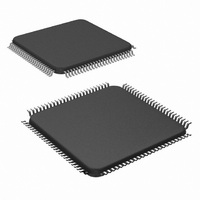
LM9830VJD/NOPB National Semiconductor, LM9830VJD/NOPB Datasheet - Page 14

LM9830VJD/NOPB
Manufacturer Part Number
LM9830VJD/NOPB
Description
IC SCANNER COLOR DOC 100-TQFP
Manufacturer
National Semiconductor
Datasheet
1.LM9830VJDNOPB.pdf
(45 pages)
Specifications of LM9830VJD/NOPB
Number Of Bits
12
Number Of Channels
3
Power (watts)
350mW
Voltage - Supply, Analog
5V
Voltage - Supply, Digital
4.5 V ~ 5.5 V
Package / Case
100-TQFP, 100-VQFP
Lead Free Status / RoHS Status
Lead free / RoHS Compliant
Other names
*LM9830VJD
*LM9830VJD/NOPB
LM9830VJD
*LM9830VJD/NOPB
LM9830VJD
Available stocks
Company
Part Number
Manufacturer
Quantity
Price
Company:
Part Number:
LM9830VJD/NOPB
Manufacturer:
Texas Instruments
Quantity:
10 000
Address
COMMAND REGISTER
MASTER CLOCK DIVIDER
HORIZONTAL RESOLUTION AND DATAMODE SETTINGS
07
08
09
Command Register
This register is used to start and end a scan.
It is also used to home the sensor in a
flatbed scanner or eject the image in a
sheetfed scanner.
Standby
When this bit is set the crystal oscillator
continues to run but all internal clock signals
are frozen. The analog circuitry is turned off
to reduce power consumption.
Reset (Host must write a 1 then a 0 to enter
and exit the reset state)
MCLK Divider
This register sets the master clock frequency
for the entire scanner.
f
f
Horizontal DPI Divider
This register determines the horizontal
resolution of the scan.
Scan resolution = Optical resolution divided
by the Horizontal_DPI_Divider.
Pixel Packing
This register determines how many bits in
each byte of data are transmitted to the host
when DataMode = 0
DataMode
When DataMode = 0, the pixel data is fully
processed, going through the Offset,
Shading, Horizontal DPI Adjust, Gamma,
and Pixel Packing blocks.
When DataMode = 1, 10 bit data is extracted
following the Horizontal DPI Adjust stage.
Gamma and any other post processing must
be done by the host.
When DataMode = 1, Horizontal DPI Adjust
= 0, and the Offset and Gain coefficients are
set to 0, the 12 bit data straight from the
ADC is transmitted. Offset, Shading,
Gamma and any other post processing must
be done by the host.
MCLK
ADC
= f
= f
MCLK
CRYSTAL
/8
/MCLK_Divider
Function
D
7
D
6
D
0 0 0 0 0 0 ÷1.0
0 0 0 0 0 1 ÷1.5
0 0 0 1 1 0 ÷4
a a a a a a ÷ ((aaaaaa/2)+1)
1 1 1 1 1 0 ÷32.0
1 1 1 1 1 1 ÷32.5
0
1
5
D
0 0
0 1
1 0
1 1
4
14
D
3
0
1
D
0
1
0 0 0 ÷1
0 0 1 ÷1.5
0 1 0 ÷2
0 1 1 ÷3
1 0 0 ÷4
1 0 1 ÷6
1 1 0 ÷8
1 1 1 ÷12
2
D
0 0
0 1
1 0
1 1
1
D
0
Idle - Stops motor (A, B, A, B = 0),
completes current line of data (if scanning).
Note: CCD/CIS clocks continue clocking.
High Speed Forward - Moves motor forward at a
speed determined by the Fast Feed Step Size
(registers 48 and 49).
High Speed Reverse - Moves motor backward at a
speed determined by the Fast Feed Step Size
(registers 48 and 49).
Start Scan - Resets the LM9830’s data pointers and
starts an image scan.
Operating
Low Power Standby Mode
Normal Operation
Resets the LM9830
1 bit/pixel (1 bit grayscale/3 bit color)
2 bits/pixel (2 bit grayscale/6 bit color)
4 bits/pixel (4 bit grayscale/12 bit color)
8 bits/pixel (8 bit grayscale/24 bit color)
1, 2, 4, or 8 bit image data,
as determined by the Pixel Size setting.
10 bit image data - sent in 2 bytes:
X X X X 9 8 7 6- 5 4 3 2 1 0 X X
12 bit image data - sent in 2 bytes:
X X X X 11 10 9 8 - 7 6 5 4 3 2 1 0,
Horizontal DPI Divider = 0.
Value
http://www.national.com


