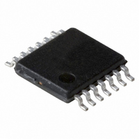
PCA2125TS/1,112 NXP Semiconductors, PCA2125TS/1,112 Datasheet - Page 22

PCA2125TS/1,112
Manufacturer Part Number
PCA2125TS/1,112
Description
IC CMOS RTC/CALENDAR 14-TSSOP
Manufacturer
NXP Semiconductors
Type
Clock/Calendar/Alarmr
Datasheet
1.PCA2125TS1112.pdf
(36 pages)
Specifications of PCA2125TS/1,112
Package / Case
14-TSSOP
Time Format
HH:MM:SS (12/24 hr)
Date Format
YY-MM-DD-dd
Interface
SPI, 3-Wire Serial
Voltage - Supply
1.3 V ~ 5.5 V
Operating Temperature
-40°C ~ 125°C
Mounting Type
Surface Mount
Function
Clock, Calendar
Supply Voltage (max)
5.5 V
Supply Voltage (min)
1.3 V
Maximum Operating Temperature
+ 125 C
Minimum Operating Temperature
- 40 C
Mounting Style
SMD/SMT
Rtc Bus Interface
Serial
Lead Free Status / RoHS Status
Lead free / RoHS Compliant
For Use With
OM6292 - DEMO BOARD PCA2125 RTC
Memory Size
-
Lead Free Status / RoHS Status
Lead free / RoHS Compliant, Lead free / RoHS Compliant
Other names
935283386112
PCA2125TS/1
PCA2125TS/1
PCA2125TS/1
PCA2125TS/1
NXP Semiconductors
PCA2125_1
Product data sheet
8.10 STOP bit function
Repeat steps 7 and 8 for additional increments.
The STOP bit function allows the accurate starting of the time circuits. The stop function
will cause the upper part of the prescaler (F
will be generated. The time circuits can then be set and will not increment until the stop is
released; see
Stop will not affect the output of 32768 Hz, 16384 Hz or 8192 Hz; see
The lower two stages of the prescaler (F
is asynchronous to the crystal oscillator, the accuracy of re-starting the time circuits will be
between 0 and one 8192 Hz cycle; see
1. Set EXT_TEST test mode (register Control_1, bit EXT_TEST = 1).
2. Set STOP (register Control_1, bit STOP = 1).
3. Clear STOP (register Control_1, bit STOP = 0).
4. Set time registers to desired value.
5. Apply 32 clock pulses to pin CLKOUT.
6. Read time registers to see the first change.
7. Apply 64 clock pulses to pin CLKOUT.
8. Read time registers to see the second change.
Fig 15. Stop bit functional diagram
Fig 16. STOP bit release timing
OSC
stop released
Figure
8192 Hz
15.
Rev. 01 — 28 July 2008
F
0
F
1
DETECTOR
OSC STOP
Figure
0
and F
2
to F
0 s to 122 s
RES
16.
F
1
2
) are not reset and because the SPI-bus
14
16384 Hz
) to be held at reset, thus no 1 Hz ticks
8192 Hz
reset
512 Hz
SPI Real-time clock/calendar
RES
F
13
CLKOUT source
RES
PCA2125
F
Section
001aaf912
© NXP B.V. 2008. All rights reserved.
14
001aaf911
1 Hz tick
stop
8.8.
22 of 36


