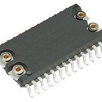
M48T201Y-70MH1E STMicroelectronics, M48T201Y-70MH1E Datasheet - Page 25

M48T201Y-70MH1E
Manufacturer Part Number
M48T201Y-70MH1E
Description
IC SUPERVISOR TIMEKPR 5V 44-SOH
Manufacturer
STMicroelectronics
Series
Timekeeper®r
Type
Clock/Calendar/NVSRAMr
Datasheet
1.M48T201V-85MH1F.pdf
(37 pages)
Specifications of M48T201Y-70MH1E
Memory Size
External
Time Format
HH:MM:SS (24 hr)
Date Format
YY-MM-DD-dd
Interface
Parallel
Voltage - Supply
4.5 V ~ 5.5 V
Operating Temperature
0°C ~ 70°C
Mounting Type
Surface Mount
Package / Case
44-SOH
Number Of Voltages Monitored
1
Monitored Voltage
3.3 V, 5 V
Manual Reset
Not Resettable
Watchdog
Watchdog
Battery Backup Switching
Backup
Supply Voltage (max)
5.5 V
Supply Voltage (min)
4.5 V
Supply Current (typ)
15000 uA
Maximum Power Dissipation
1000 mW
Maximum Operating Temperature
+ 70 C
Mounting Style
SMD/SMT
Minimum Operating Temperature
0 C
Power Fail Detection
Yes
Lead Free Status / RoHS Status
Contains lead / RoHS non-compliant
Other names
497-2840-5
M48T201Y-70MH1
M48T201Y-70MH1
M48T201Y, M48T201V
Note:
3.12
If a battery low indication is generated during the 24-hour interval check, this indicates that
the battery is near end of life. However, data is not compromised due to the fact that a
nominal V
battery backup mode, the battery should be replaced. The SNAPHAT
while V
This will cause the clock to lose time during the interval the battery/crystal is removed.
The M48T201Y/V only monitors the battery when a nominal V
Thus applications which require extensive durations in the battery backup mode should be
powered-up periodically (at least once every few months) in order for this technique to be
beneficial. Additionally, if a battery low is indicated, data integrity should be verified upon
power-up via a checksum or other technique.
Initial power-on defaults
Upon application of power to the device, the following register bits are set to a '0' state:
WDS; BMB0-BMB4; RB0-RB1; AFE; ABE; SQWE; W; R; FT (see
Table 9.
1. WDS, BMB0-BMB4, RB0, RB1.
2. State of other control bits undefined.
3. State of other control bits remains unchanged.
4. Assuming these bits set to '1' prior to power-down.
Initial power-up
(Battery attach for
SNAPHAT)
Power-down
RESET
CC
(3)
Condition
CC
is applied to the device.
(2)
(4)
Default values
is supplied. In order to insure data integrity during subsequent periods of
W
0
0
0
R
0
0
0
FT
0
0
0
AFE
0
0
1
CC
ABE
0
0
1
is applied to the device.
Table
®
SQWE
top may be replaced
9).
0
0
1
Clock operation
Watchdog
register
0
0
0
25/37
(1)


