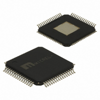
SY89538LHG TR Micrel Inc, SY89538LHG TR Datasheet - Page 19

SY89538LHG TR
Manufacturer Part Number
SY89538LHG TR
Description
IC SYNTHESIZR LVPECL/LVDS 64TQFP
Manufacturer
Micrel Inc
Series
Precision Edge®r
Type
Clock Synthesizer/Fanout Bufferr
Datasheet
1.SY89538LHH.pdf
(23 pages)
Specifications of SY89538LHG TR
Pll
Yes
Input
CMOS, HSTL, LVDS, LVPECL, LVTTL, SSTL, Crystal
Output
LVDS, LVPECL
Number Of Circuits
1
Ratio - Input:output
2:7
Differential - Input:output
Yes/Yes
Frequency - Max
756MHz
Divider/multiplier
Yes/No
Voltage - Supply
2.375 V ~ 3.6 V
Operating Temperature
-40°C ~ 85°C
Mounting Type
Surface Mount
Package / Case
64-TQFP Exposed Pad, 64-eTQFP, 64-HTQFP, 64-VQFP
Frequency-max
756MHz
Lead Free Status / RoHS Status
Lead free / RoHS Compliant
Other names
SY89538LHGTR
SY89538LHGTR
SY89538LHGTR
Figure 6 shows the open and closed loop gain of the
SY89538L. The closed loop-gain plot shows that the
SY89538L when configured with the recommended
loop filter values has essentially no jitter peaking near
the -3dB point. In addition, the open loop curve shows
the frequency at which unity gain occurs for a typical
case of the SY89538L with V
At unity gain, Figure 7 can be used to determine the
phase margin or stability of the SY89538L.
Figure 8 illustrates the VCO frequency versus the loop
filter control voltage at 3.3V, T
loop filter control voltage is -300mV to +300mV.
Figure 9 illustrates the VCO gain curve at V
T
the loop stability with other sets of loop filter
configurations is possible.
June 2006
A
= 25°C. With this set of information, determining
Figure 6. Open and Closed Loop Gain
Figure 7. Phase Margin Plot
at V
at V
CC
CC
= 3.3V, T
= 3.3V, T
Frequency (Hz)
Frequency (Hz)
CC
A
A
A
= 25°C
= 25°C
= 3.3V at T
= 25°C. The normal
CC
A
= 25°C.
= 3.3V,
19
Input Interface
RFCK and FBIN are designed to accept any
differential or single-ended input signal 300mV above
V
not be left floating. Tie either the true or complement
input to GND, but not both. A logic zero is achieved by
connecting the complement input to GND with the true
input floating. For TTL input, tie a 2.5kΩ resistor
between the complement input and GND. LVDS, CML
and HSTL differential signals may be connected
directly to the reference inputs.
CC
or 300mV below GND. RFCK and FBIN should
Loop Filter Control Voltage at 3.3V, T
Figure 8. Loop Filter Control Voltage vs.
Figure 10. Simplified Input Structure
Frequency at 3.3V, T
Figure 9. Frequency vs.
hbwhelp@micrel.com
A
= 25°C
or (408) 955-1690
M9999-062706-D
A
= 25°C


