ICS9DB1200CGLF IDT, Integrated Device Technology Inc, ICS9DB1200CGLF Datasheet - Page 4
ICS9DB1200CGLF
Manufacturer Part Number
ICS9DB1200CGLF
Description
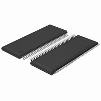
IC BUFFER 12OUTPUT DIFF 64-TSSOP
Manufacturer
IDT, Integrated Device Technology Inc
Type
Clock Bufferr
Series
-r
Datasheet
1.ICS9DB1200CGLFT.pdf
(14 pages)
Specifications of ICS9DB1200CGLF
Input
Differential
Output
Differential
Frequency - Max
400MHz
Voltage - Supply
3.135 V ~ 3.465 V
Operating Temperature
0°C ~ 70°C
Mounting Type
Surface Mount
Package / Case
64-TSSOP
Frequency-max
400MHz
Lead Free Status / RoHS Status
Lead free / RoHS Compliant
Other names
9DB1200CGLF
Available stocks
Company
Part Number
Manufacturer
Quantity
Price
Company:

Part Number:
ICS9DB1200CGLF
Manufacturer:
IDT
Quantity:
124
Part Number:
ICS9DB1200CGLF
Manufacturer:
IDT
Quantity:
20 000
Part Number:
ICS9DB1200CGLFT
Manufacturer:
IDT
Quantity:
20 000


Pin Description
IDT
PIN #
ICS9DB1200C
Twelve Output Differential Buffer for PCIe Gen1/Gen2, QPI, and FBDIMM
33
34
35
36
37
38
39
40
41
42
43
44
45
46
47
48
49
50
51
52
53
54
55
56
57
58
59
60
61
62
63
64
TM
/ICS
TM
SMBDAT
FS1
BYPASS#/PLL
VTTPWRGD#/PD
DIF_6#
DIF_6
OE6#
GND
VDD
DIF_7#
DIF_7
OE7#
DIF_8#
DIF_8
OE8#
VDD
GND
DIF_9#
DIF_9
OE9#
DIF_10#
DIF_10
OE10#
GND
VDD
DIF_11#
DIF_11
OE11#
FS0
IREF
AGND
VDDA
Twelve Output Differential Buffer for PCIe Gen1/Gen2, QPI, and FBDIMM
PIN NAME
TYPE
OUT
OUT
PWR
PWR
OUT
OUT
OUT
OUT
PWR
PWR
OUT
OUT
OUT
OUT
PWR
PWR
OUT
OUT
OUT
PWR
PWR
I/O
IN
IN
IN
IN
IN
IN
IN
IN
IN
IN
Data pin of SMBUS circuitry, 5V tolerant
3.3V Frequency select latched input pin.
Input to select Bypass(fan-out) or PLL (ZDB) mode
0 = Bypass mode, 1= PLL mode
VTTPWRGD# is an active low input used to sample latched inputs and
allow the device to Power Up. PD is an asynchronous active high input
pin used to put the device into a low power state. The internal clocks and
PLLs are stopped.
0.7V differential complement clock output
0.7V differential true clock output
Active low input for enabling DIF pair 6.
1 = tri-state outputs, 0 = enable outputs
Ground pin.
Power supply, nominal 3.3V
0.7V differential complement clock output
0.7V differential true clock output
Active low input for enabling DIF pair 7.
1 = tri-state outputs, 0 = enable outputs
0.7V differential complement clock output
0.7V differential true clock output
Active low input for enabling DIF pair 8.
1 = tri-state outputs, 0 = enable outputs
Power supply, nominal 3.3V
Ground pin.
0.7V differential complement clock output
0.7V differential true clock output
Active low input for enabling DIF pair 9.
1 = tri-state outputs, 0 = enable outputs
0.7V differential complement clock output
0.7V differential true clock output
Active low input for enabling DIF pair 10.
1 = tri-state outputs, 0 = enable outputs
Ground pin.
Power supply, nominal 3.3V
0.7V differential complement clock output
0.7V differential true clock output
Active low input for enabling DIF pair 11.
1 = tri-state outputs, 0 = enable outputs
3.3V Frequency select latched input pin.
This pin establishes the reference current for the differential current-
mode output pairs. This pin requires a fixed precision resistor tied to
ground in order to establish the appropriate current. 475 ohms is the
standard value.
Analog Ground pin for Core PLL
3.3V power for the PLL core.
4
DESCRIPTION
1414E—11/04/09
Related parts for ICS9DB1200CGLF
Image
Part Number
Description
Manufacturer
Datasheet
Request
R

Part Number:
Description:
TRANSLATION DEVICE DPI 80-PQFP
Manufacturer:
IDT, Integrated Device Technology Inc
Datasheet:
Part Number:
Description:
IDT PART
Manufacturer:
IDT, Integrated Device Technology Inc
Datasheet:
Part Number:
Description:
IC LIU T1/E1/J1 OCTAL 256PBGA
Manufacturer:
IDT, Integrated Device Technology Inc
Datasheet:

Part Number:
Description:
IC FREQ TIMING GENERATOR 28TSSOP
Manufacturer:
IDT, Integrated Device Technology Inc
Datasheet:
Part Number:
Description:
IC CLK DVR PLL 1:10 40VFQFPN
Manufacturer:
IDT, Integrated Device Technology Inc
Datasheet:
Part Number:
Description:
IC CLK FANOUT BUFFER 1:18 32LQFP
Manufacturer:
IDT, Integrated Device Technology Inc
Datasheet:
Part Number:
Description:
IC CLK FANOUT BUFFER 1:18 32LQFP
Manufacturer:
IDT, Integrated Device Technology Inc
Datasheet:
Part Number:
Description:
IC CK505 VREG/RES 56TSSOP
Manufacturer:
IDT, Integrated Device Technology Inc
Datasheet:

Part Number:
Description:
IC SDRAM CLK DVR 1:10 48-TSSOP
Manufacturer:
IDT, Integrated Device Technology Inc
Datasheet:

Part Number:
Description:
IC CLK DVR PLL 1:10 48TSSOP
Manufacturer:
IDT, Integrated Device Technology Inc
Datasheet:
Part Number:
Description:
IC FLEXPC CLK PROGR P4 56-TSSOP
Manufacturer:
IDT, Integrated Device Technology Inc
Datasheet:
Part Number:
Description:
IC FLEXPC CLK PROGR P4 56-TSSOP
Manufacturer:
IDT, Integrated Device Technology Inc
Datasheet:
Part Number:
Description:
IC FLEXPC CLK PROGR P4 56-SSOP
Manufacturer:
IDT, Integrated Device Technology Inc
Datasheet:

Part Number:
Description:
IC PLL CLK DRIVER 2.5V 28-TSSOP
Manufacturer:
IDT, Integrated Device Technology Inc
Datasheet:
Part Number:
Description:
IC CLOCK DRIVER 2.5V 24-TSSOP
Manufacturer:
IDT, Integrated Device Technology Inc
Datasheet: