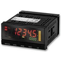
K3HB-SSD 24VACVDC Omron, K3HB-SSD 24VACVDC Datasheet - Page 21

K3HB-SSD 24VACVDC
Manufacturer Part Number
K3HB-SSD 24VACVDC
Description
SENS LINEAR METER DC PROCES INPT
Manufacturer
Omron
Series
K3HBr
Type
Linear Sensor Meterr
Specifications of K3HB-SSD 24VACVDC
Measuring Range
0 ~ 20mA, 0 ~ 10V
Display Style
Green, Red Characters, Black Background
Display Type
LCD
Display Face Size
3.78" L x 1.89" W (96.0 x 48.0mm)
Display Digits
5
Display Digits - Height
0.193" (4.90mm), 0.559" (14.20mm)
Backlight
Green, Red
Mounting Type
Panel Mount
Termination
Screw Terminals
Voltage - Supply
24VAC/DC
Power Consumption
7W
Svhc
No SVHC (15-Dec-2010)
External Depth
95mm
External Length / Height
48mm
Ip/nema Rating
IP20
Operating Temperature Max
55°C
Operating Temperature Min
-10°C
Supply Voltage
RoHS Compliant
Approval Bodies
CE, CRUus, UL
Current Consumption
50mA
Rohs Compliant
Yes
Lead Free Status / RoHS Status
Lead free / RoHS Compliant
For Use With
High-speed, High-precision
Lead Free Status / RoHS Status
Lead free / RoHS Compliant
Other names
K3HB-SSD24VACVDC
K3HBSSD24VACVDC
K3HBSSD24VACVDC
DeviceNet Communications
■ Internal Block Diagram
Communications protocol
Supported communi-
cations
Connection methods
Baud rate
Communications media
Communications distance
Communications power supply
Allowable voltage fluctuation range
Current consumption
Maximum number of nodes
Maximum number of slaves
Error control checks
DeviceNet power supply
Sensor power
Linear output
Analog input
Event input
BCD I/O
supply
Digital input
Linear output
• Input circuit
• Output circuit
• Transistor
output circuit
circuit
Input
BCD
circuit
circuit
Filter
V
O
Remote I/O communications
I/O allocations
Message communications
Power supply circuit (isolated)
shaping circuit
EEP-ROM
Waveform
circuit
circuit
Drive
Drive
ADC
Power supply
computer
Micro-
V
DD
Indications
circuit
circuit
circuit
circuit
Keys
Drive
Drive
Drive
Drive
Conforms to DeviceNet
Master-Slave connection (polling, bit-strobe, COS, cyclic)
Conforms to DeviceNet communications standards.
Allocate any I/O data using the Configurator.
Allocate any data, such as DeviceNet-specific parameters and variable area for Digital
Indicators.
Input area: 2 blocks, 60 words max.
Output area: 1 block, 29 words max.
(The first word in the area is always allocated for the Output Execution Enabled Flags.)
Explicit message communications
CompoWay/F communications commands can be executed (using explicit message
communications)
Combination of multi-drop and T-branch connections (for trunk and drop lines)
DeviceNet: 500, 250, or 125 Kbps (automatic follow-up)
Special 5-wire cable (2 signal lines, 2 power supply lines, 1 shield line)
24-VDC DeviceNet power supply
11 to 25-VDC DeviceNet power supply
50 mA max. (24 VDC)
64 (DeviceNet Configurator is counted as one node when connected)
63
CRC errors
Supplied from DeviceNet communications connector
500 Kbps
250 Kbps
125 Kbps
The values in parentheses are for Thick Cable.
X
Baud rate
V
O
Converter (isolated)
DeviceNet
Communi-
DC-DC
cations
circuit
driver
V
Digital Indicators
COM
100 m (100 m)
100 m
(250 m)
100 m
(500 m)
Network length
Transistor
output
Relay output
DeviceNet
Communications
(max.)
K3HB-X/-V/-H/-S
6 m
6 m
6 m
Drop line length
(max.)
39 m
78 m
156 m
Total drop line
length (max.)
21


