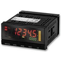
K3HB-SSD 24VACVDC Omron, K3HB-SSD 24VACVDC Datasheet - Page 19

K3HB-SSD 24VACVDC
Manufacturer Part Number
K3HB-SSD 24VACVDC
Description
SENS LINEAR METER DC PROCES INPT
Manufacturer
Omron
Series
K3HBr
Type
Linear Sensor Meterr
Specifications of K3HB-SSD 24VACVDC
Measuring Range
0 ~ 20mA, 0 ~ 10V
Display Style
Green, Red Characters, Black Background
Display Type
LCD
Display Face Size
3.78" L x 1.89" W (96.0 x 48.0mm)
Display Digits
5
Display Digits - Height
0.193" (4.90mm), 0.559" (14.20mm)
Backlight
Green, Red
Mounting Type
Panel Mount
Termination
Screw Terminals
Voltage - Supply
24VAC/DC
Power Consumption
7W
Svhc
No SVHC (15-Dec-2010)
External Depth
95mm
External Length / Height
48mm
Ip/nema Rating
IP20
Operating Temperature Max
55°C
Operating Temperature Min
-10°C
Supply Voltage
RoHS Compliant
Approval Bodies
CE, CRUus, UL
Current Consumption
50mA
Rohs Compliant
Yes
Lead Free Status / RoHS Status
Lead free / RoHS Compliant
For Use With
High-speed, High-precision
Lead Free Status / RoHS Status
Lead free / RoHS Compliant
Other names
K3HB-SSD24VACVDC
K3HBSSD24VACVDC
K3HBSSD24VACVDC
The range shown in dark shading indicates the factory setting.
Sampling and Comparative Output Response Times
The K3HB-S sampling and comparative output response times depend on the calculation methods, timing hold type, and, for simple averaging, the
averaging times. Refer to the following description for details.
■ Output Refresh Period
The K3HB-S repeats input reads, calculation, and judgement output
processing. The output refresh period differs depending on whether
there are one or two inputs, as outlined below.
One Input
Two inputs
Input A
Input A
Input B
DC current
range (mA)
Input B
Connected terminals
Input A
Input B
or
or
Input
↓
Input
↓
Input read
Input read
0.5 ms
Output
refresh
Output
refresh
0.5 ms
Input type
in-ta
in-tb
Output
↓
Output
24.000
20.000
16.000
12.000
− 4.000
Input
8.000
4.000
0.000
Input
↓
Input A: Every 1 ms
Input B: Every 1 ms
Every 0.5 ms
Every 0.5 ms
Every 0.5 ms
0.5 ms
0.5 ms
↓
Output
↓
Output
Input
↓
Input
↓
0.5 ms
0.5 ms
22.000
− 2.000
0-20
DC current input
Output
↓
Output
Input
Input
↓
E2
E1
↓
Output
E3
E3
↓
Output
Input
↓
Input
↓
22.000
4-20
2.000
Output
↓
Output
Input
Input
↓
Input A
Input B
DC voltage
range (V)
↓
Output
Connected terminals
Input
↓
0.5 ms
0.5 ms
Input type
■ Output Response Time
The comparative output response time is the sum of the data pro-
cessing time and the output (relay or transistor) response time.
One Input
Two Inputs
Note: For transistor outputs:
in-ta
in-tb
− 10.000
10.000
− 5.000
5.000
0.000
For relay outputs:
0.5 ms
0.5 ms
R
R
Linear Sensor Indicator
For one input: OFF to ON 1 ms and ON to OFF 1.5 ms
For two inputs: OFF to ON 2 ms and ON to OFF 2.5 ms
The relay operation time of 15 ms is added to the transistor
output response times.
− 0.500
5.500
0-5
0.5 ms
0.5 ms
R
R
0.5 ms
R
R
5.500
0.500
1-5
DC voltage input
E4
E5
R
K3HB-S
E3
E3
− 5.500
5.500
5
R
R
(See note.)
(See note.)
Output response time
Data processing time
Output response time
Data processing time
− 11.000
11.000
10
19


