HW-FMC-XM104-G Xilinx Inc, HW-FMC-XM104-G Datasheet - Page 8
HW-FMC-XM104-G
Manufacturer Part Number
HW-FMC-XM104-G
Description
CARD, CONNECTIVITY, FMC XM104
Manufacturer
Xilinx Inc
Datasheet
1.HW-FMC-XM104-G.pdf
(20 pages)
Specifications of HW-FMC-XM104-G
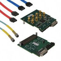
Kit Contents
FMC XM104 Connectivity Card, 4x SMA To SMA Cables, SATA Cable, Welcome Letter
Features
VITA 57.1 FMC High Pin Count (HPC) Connector
Accessory Type
Interface Board
Lead Free Status / RoHS Status
Lead free / RoHS Compliant
For Use With/related Products
Xilinx FMC-Supported Boards
Lead Free Status / RoHS Status
Lead free / RoHS Compliant, Lead free / RoHS Compliant
Other names
122-1693


Chapter 1: XM104
8
Package Contents
Necessary Equipment
System Setup
Software
Example designs that use this hardware are not provided at this time.
The following items are included in the XM104 shipment:
•
•
•
•
•
•
•
•
•
Complete the following steps to install the XM104 to a Xilinx board. For additional
information on Xilinx boards, refer to the board’s user guide. See
Documentation, page
1.
2.
3.
4.
5.
6.
7.
The system is now ready for use.
XM104 card
Four (4) mounting screws
Two (2) standoffs
Four (4) SMA-P to SMA-P cables
Serial ATA loopback cable
Serial ATA cable
Welcome letter
Small Phillips screwdriver to secure the XM104 to the board
PC with Internet access to download documentation, board files, and schematics
Turn off the DC power switch and disconnect the input power source from the board.
Remove the XM104 from the electrostatic device (ESD) bag.
Using a small Phillips screwdriver, remove the two screws from the bottom side of the
two standoffs on the XM104. These screws will be used to attach the board to the
standoffs attached to the XM104.
Install the XM104 to the ML605 FMC HPC connector J64. The XM104 hangs off the
edge of the board as shown in
Turn the attached board and XM104 such that the FPGA is facing the table. Install two
screws from the bottom side of board's FMC mounting holes into the two standoffs
attached to the XM104. Hand tighten the two mounting screws to the bottom of the
board.
Turn the attached board and XM104 unit over such that the Xilinx FPGA is visible.
Connect the input power source to the board. Turn the board power input switch to
ON.
5.
www.xilinx.com
Figure 1-1, page
FMC XM104 Connectivity Card User Guide
9.
UG536 (v1.1) September 24, 2010
Additional
Related parts for HW-FMC-XM104-G
Image
Part Number
Description
Manufacturer
Datasheet
Request
R

Part Number:
Description:
CARD, CONNECTIVITY, FMC XM105
Manufacturer:
Xilinx Inc
Datasheet:
Part Number:
Description:
HARDWARE FMC-VIDEO DAUGHTER CARD
Manufacturer:
Xilinx Inc
Datasheet:
Part Number:
Description:
HARDWARE FMC INTERFACE CARD
Manufacturer:
Xilinx Inc
Datasheet:

Part Number:
Description:
IC CPLD .8K 36MCELL 44-VQFP
Manufacturer:
Xilinx Inc
Datasheet:

Part Number:
Description:
IC CPLD 72MCRCELL 10NS 44VQFP
Manufacturer:
Xilinx Inc
Datasheet:

Part Number:
Description:
IC CPLD 1.6K 72MCELL 64-VQFP
Manufacturer:
Xilinx Inc
Datasheet:

Part Number:
Description:
IC CR-II CPLD 64MCELL 44-VQFP
Manufacturer:
Xilinx Inc
Datasheet:

Part Number:
Description:
IC CPLD 1.6K 72MCELL 100-TQFP
Manufacturer:
Xilinx Inc
Datasheet:

Part Number:
Description:
IC CR-II CPLD 64MCELL 56-BGA
Manufacturer:
Xilinx Inc
Datasheet:

Part Number:
Description:
IC CPLD 72MCRCELL 7.5NS 44VQFP
Manufacturer:
Xilinx Inc
Datasheet:
Part Number:
Description:
IC CR-II CPLD 64MCELL 100-VQFP
Manufacturer:
Xilinx Inc
Datasheet:
Part Number:
Description:
IC CPLD 1.6K 72MCELL 100-TQFP
Manufacturer:
Xilinx Inc
Datasheet:

Part Number:
Description:
IC CPLD 72MCRCELL 7.5NS 64VQFP
Manufacturer:
Xilinx Inc
Datasheet:
Part Number:
Description:
IC CPLD 1.6K 72MCELL 100-TQFP
Manufacturer:
Xilinx Inc
Datasheet:

Part Number:
Description:
IC CPLD 1.5K 64MCELL HP 44-VQFP
Manufacturer:
Xilinx Inc