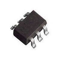
BGA2011 T/R NXP Semiconductors, BGA2011 T/R Datasheet - Page 3

BGA2011 T/R
Manufacturer Part Number
BGA2011 T/R
Description
RF Amplifier TAPE-7 MMIC-RFS
Manufacturer
NXP Semiconductors
Type
Low Noise Wideband Amplifierr
Datasheet
1.BGA2011115.pdf
(12 pages)
Specifications of BGA2011 T/R
Operating Frequency
0.9 GHz
Noise Figure
1.5 dB
Operating Supply Voltage
3 V
Supply Current
15 mA
Maximum Power Dissipation
135 mW
Maximum Operating Temperature
+ 150 C
Mounting Style
SMD/SMT
Package / Case
SOT-363
Number Of Channels
1 Channel
Lead Free Status / RoHS Status
Lead free / RoHS Compliant
Other names
BGA2011,115
NXP Semiconductors
THERMAL CHARACTERISTICS
CHARACTERISTICS
RF input AC coupled; V
2000 Dec 04
R
I
I
R
R
|s
NF
IP3
S
C
SYMBOL
900 MHz high linear low noise amplifier
th j-s
L IN
L OUT
21
SYMBOL
in
|
2
supply current
control current
return losses input
return losses output
insertion power gain
noise figure
input intercept point
thermal resistance from junction
to solder point
PARAMETER
S
= 3 V; I
PARAMETER
S
= 15 mA; f = 900 MHz; T
typical application; see Fig.2
high IP3 (see Fig.2; stripline = 0 mm)
high IP3 (see Fig.2; stripline = 1.5 mm)
typical application; see Fig.2
high IP3 (see Fig.2; stripline = 0 mm)
high IP3 (see Fig.2; stripline = 1.5 mm)
typical application; see Fig.2
high IP3 (see Fig.2; stripline = 0 mm)
high IP3 (see Fig.2; stripline = 1.5 mm)
typical application; see Fig.2;
I
high IP3 (see Fig.2; stripline = 0 mm)
high IP3 (see Fig.2; stripline = 1.5 mm)
typical application; see Fig.2
high IP3 (see Fig.2; stripline = 0 mm)
high IP3 (see Fig.2; stripline = 1.5 mm)
S
= 15 mA
P
tot
CONDITIONS
= 135 mW; T
3
j
CONDITIONS
= 25 C; unless otherwise specified.
s
100 C
10
MIN.
VALUE
350
15
0.11
11
11
17
11
12
14
15
19
16
1.5
1.6
1.7
2
4
10
TYP.
Product specification
20
BGA2011
MAX.
UNIT
K/W
dB
mA
mA
dB
dB
dB
dB
dB
dB
dB
dB
dB
dB
dB
dBm
dBm
dBm
UNIT


