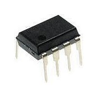
ATTINY12L-4PU Atmel, ATTINY12L-4PU Datasheet - Page 30

ATTINY12L-4PU
Manufacturer Part Number
ATTINY12L-4PU
Description
MCU 8-Bit ATtiny AVR RISC 1KB Flash 3.3V/5V 8-Pin PDIP
Manufacturer
Atmel
Datasheet
1.ATTINY12V-1SI.pdf
(94 pages)
Specifications of ATTINY12L-4PU
Package
8PDIP
Device Core
AVR
Family Name
ATtiny
Maximum Speed
4 MHz
Operating Supply Voltage
3.3|5 V
Data Bus Width
8 Bit
Number Of Programmable I/os
6
Interface Type
SPI
Number Of Timers
1
Program Memory Size
1 KB
Program Memory Type
Flash
Operating Temperature
-40 to 85 °C
Processor Series
ATTINY1x
Core
AVR8
Maximum Clock Frequency
4 MHz
Maximum Operating Temperature
+ 85 C
Mounting Style
Through Hole
Package / Case
PDIP-8
3rd Party Development Tools
EWAVR, EWAVR-BL
Development Tools By Supplier
ATAVRDRAGON, ATSTK500
Minimum Operating Temperature
- 40 C
Lead Free Status / Rohs Status
Details
Interrupts
Reset and Interrupt
30
ATtiny11/12
The ATtiny11 provides four different interrupt sources and the ATtiny12 provides five.
These interrupts and the separate reset vector each have a separate program vector in
the program memory space. All the interrupts are assigned individual enable bits which
must be set (one) together with the I-bit in the status register in order to enable the
interrupt.
The lowest addresses in the program memory space are automatically defined as the
Reset and Interrupt vectors. The complete list of vectors is shown in Table 14. The list
also determines the priority levels of the different interrupts. The lower the address, the
higher the priority level. RESET has the highest priority, and next is INT0 – the External
Interrupt Request 0, etc.
Table 14. Reset and Interrupt Vectors
The most typical and general program setup for the reset and interrupt vector addresses
for the ATtiny11 are:
The most typical and general program setup for the reset and interrupt vector addresses
for the ATtiny12 are:
Vector No.
Address
$000
$001
$002
$003
$004
;
$005
Address
$000
$001
$002
$003
1
1
2
3
4
5
5
6
…
Labels
MAIN:
Labels
ATtiny11/12
ATtiny11/12
ATtiny11/12
ATtiny11
ATtiny12
ATtiny11
ATtiny12
ATtiny12
…
Device
Code
rjmp
rjmp
rjmp
rjmp
rjmp
<instr>
Code
rjmp
rjmp
rjmp
rjmp
…
Program Address
$000
$000
$001
$002
$003
$004
$004
$005
xxx
RESET
EXT_INT0
PIN_CHANGE
TIM0_OVF
ANA_COMP
…
RESET
EXT_INT0
PIN_CHANGE
TIM0_OVF
TIMER0, OVF0
ANA_COMP
ANA_COMP
EE_RDY
Comments
; Reset handler
; IRQ0 handler
; Pin change handler
; Timer0 overflow handler
; Analog Comparator handler
; Main program start
Comments
; Reset handler
; IRQ0 handler
; Pin change handler
; Timer0 overflow handler
I/O Pins
Source
RESET
RESET
INT0
Interrupt Definition
External Pin, Power-on
Reset and Watchdog
Reset
External Pin, Power-on
Reset, Brown-out Reset
and Watchdog Reset
External Interrupt
Request 0
Pin Change Interrupt
Timer/Counter0
Overflow
Analog Comparator
EEPROM Ready
Analog Comparator
1006F–AVR–06/07


