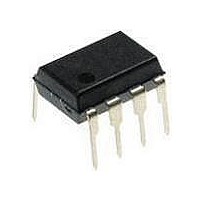
ATTINY12L-4PU Atmel, ATTINY12L-4PU Datasheet - Page 20

ATTINY12L-4PU
Manufacturer Part Number
ATTINY12L-4PU
Description
MCU 8-Bit ATtiny AVR RISC 1KB Flash 3.3V/5V 8-Pin PDIP
Manufacturer
Atmel
Datasheet
1.ATTINY12V-1SI.pdf
(94 pages)
Specifications of ATTINY12L-4PU
Package
8PDIP
Device Core
AVR
Family Name
ATtiny
Maximum Speed
4 MHz
Operating Supply Voltage
3.3|5 V
Data Bus Width
8 Bit
Number Of Programmable I/os
6
Interface Type
SPI
Number Of Timers
1
Program Memory Size
1 KB
Program Memory Type
Flash
Operating Temperature
-40 to 85 °C
Processor Series
ATTINY1x
Core
AVR8
Maximum Clock Frequency
4 MHz
Maximum Operating Temperature
+ 85 C
Mounting Style
Through Hole
Package / Case
PDIP-8
3rd Party Development Tools
EWAVR, EWAVR-BL
Development Tools By Supplier
ATAVRDRAGON, ATSTK500
Minimum Operating Temperature
- 40 C
Lead Free Status / Rohs Status
Details
Sleep Modes
Sleep Modes for the
ATtiny11
Idle Mode
Power-down Mode
Sleep Modes for the
ATtiny12
Idle Mode
Power-down Mode
20
ATtiny11/12
To enter the sleep modes, the SE bit in MCUCR must be set (one) and a SLEEP instruc-
tion must be executed. The SM bit in the MCUCR register selects which sleep mode
(Idle or Power-down) will be activated by the SLEEP instruction. If an enabled interrupt
occurs while the MCU is in a sleep mode, the MCU awakes, executes the interrupt rou-
tine, and resumes execution from the instruction following SLEEP. On wake-up from
Power Down Mode on pin change, two instruction cycles are executed before the pin
change interrupt flag is updated. During these cycles, the prosessor executes intruc-
tions, but the interrupt condition is not readable, and the interrupt routine has not startet
yet. The contents of the register file and I/O memory are unaltered. If a reset occurs dur-
ing Sleep Mode, the MCU wakes up and executes from the Reset vector.
When the SM bit is cleared (zero), the SLEEP instruction forces the MCU into the Idle
Mode, stopping the CPU but allowing Timer/Counters, Watchdog and the interrupt sys-
tem to continue operating. This enables the MCU to wake up from external triggered
interrupts as well as internal ones like Timer Overflow interrupt and Watchdog Reset. If
wake-up from the Analog Comparator interrupt is not required, the analog comparator
can be powered down by setting the ACD-bit in the Analog Comparator Control and Sta-
tus register – ACSR. This will reduce power consumption in Idle Mode. When the MCU
wakes up from Idle mode, the CPU starts program execution immediately.
When the SM bit is set (one), the SLEEP instruction forces the MCU into the Power-
down Mode. In this mode, the external oscillator is stopped, while the external interrupts
and the Watchdog (if enabled) continue operating. Only an external reset, a watchdog
reset (if enabled), an external level interrupt (INT0), or an pin change interrupt can wake
up the MCU.
Note that if a level-triggered or pin change interrupt is used for wake-up from power-
down, the changed level must be held for a time longer than the reset delay period of
t
To enter the sleep modes, the SE bit in MCUCR must be set (one) and a SLEEP instruc-
tion must be executed. The SM bit in the MCUCR register selects which sleep mode
(Idle or Power-down) will be activated by the SLEEP instruction. If an enabled interrupt
occurs while the MCU is in a sleep mode, the MCU awakes. The CPU is then halted for
four cycles, it executes the interrupt routine, and resumes execution from the instruction
following SLEEP. The contents of the register file and I/O memory are unaltered. If a
reset occurs during sleep mode, the MCU wakes up and executes from the Reset
vector.
When the SM bit is cleared (zero), the SLEEP instruction forces the MCU into the Idle
Mode stopping the CPU but allowing Timer/Counters, Watchdog and the interrupt sys-
tem to continue operating. This enables the MCU to wake up from external triggered
interrupts as well as internal ones like Timer Overflow interrupt and Watchdog Reset. If
wake-up from the Analog Comparator interrupt is not required, the analog comparator
can be powered down by setting the ACD-bit in the Analog Comparator Control and Sta-
tus Register – ACSR. This will reduce power consumption in Idle Mode.
When the SM bit is set (one), the SLEEP instruction forces the MCU into the Power-
down Mode. In this mode, the external oscillator is stopped, while the external interrupts
and the Watchdog (if enabled) continue operating. Only an external reset, a watchdog
TOUT
. Otherwise, the MCU will fail to wake up.
1006F–AVR–06/07


