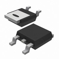
BT150S-600R,118 NXP Semiconductors, BT150S-600R,118 Datasheet - Page 3

BT150S-600R,118
Manufacturer Part Number
BT150S-600R,118
Description
THYRISTOR 600V 4A SOT428
Manufacturer
NXP Semiconductors
Datasheet
1.BT150S-600R118.pdf
(6 pages)
Specifications of BT150S-600R,118
Package / Case
DPak, TO-252 (2 leads+tab), SC-63
Scr Type
Sensitive Gate
Voltage - Off State
600V
Voltage - Gate Trigger (vgt) (max)
1.5V
Voltage - On State (vtm) (max)
1.8V
Current - On State (it (av)) (max)
2.5A
Current - On State (it (rms)) (max)
4A
Current - Gate Trigger (igt) (max)
200µA
Current - Hold (ih) (max)
6mA
Current - Off State (max)
500µA
Current - Non Rep. Surge 50, 60hz (itsm)
35A, 38A
Operating Temperature
-40°C ~ 125°C
Mounting Type
Surface Mount
Current - On State (it (rms) (max)
4A
Breakover Current Ibo Max
38 A
Rated Repetitive Off-state Voltage Vdrm
600 V
Off-state Leakage Current @ Vdrm Idrm
0.5 mA
Forward Voltage Drop
1.8 V
Gate Trigger Voltage (vgt)
1.5 V
Maximum Gate Peak Inverse Voltage
5 V
Gate Trigger Current (igt)
0.2 mA
Holding Current (ih Max)
6 mA
Mounting Style
SMD/SMT
Lead Free Status / RoHS Status
Lead free / RoHS Compliant
Other names
934048900118
BT150S-600R /T3
BT150S-600R /T3
BT150S-600R /T3
BT150S-600R /T3
Available stocks
Company
Part Number
Manufacturer
Quantity
Price
Company:
Part Number:
BT150S-600R,118
Manufacturer:
NXP Semiconductors
Quantity:
7 200
Philips Semiconductors
October 1997
Thyristors
logic level
Fig.1. Maximum on-state dissipation, P
Fig.2. Maximum permissible non-repetitive peak
6
5
4
3
2
1
0
Fig.3. Maximum permissible rms current I
1000
0
on-state current I
100
5
4
3
2
2
1
0
0
Ptot / W
-50
10
IT(RMS) / A
10us
conduction
angle
degrees
versus mounting base temperature T
ITSM / A
30
60
90
120
180
average on-state current, I
T I
Tj initial = 25 C max
0.5
sinusoidal currents, t
dI /dt limit
form
factor
a = form factor = I
T
4
2.8
2.2
1.9
1.57
T
a
I TSM
0
time
4
1
100us
TSM
IF(AV) / A
, versus pulse width t
BT148
2.8
BT148Z
Tmb / C
1.5
BT148
T / s
50
2.2
T(RMS)
p
2
1ms
1.9
T(AV)
/ I
10ms.
T(AV)
100
, where
Tmb(max) / C
2.5
.
111 C
tot
a = 1.57
, versus
mb
T(RMS)
p
, for
.
10ms
3
107
110
113
116
119
122
125
,
3
Fig.5. Maximum permissible repetitive rms on-state
current I
V
on-state current I
Fig.4. Maximum permissible non-repetitive peak
GT
1.6
1.4
1.2
0.8
0.6
0.4
10
30
20
40
12
10
0
1
0.01
(T
1
8
6
4
2
0
-50
ITSM / A
IT(RMS) / A
VGT(25 C)
j
VGT(Tj)
Fig.6. Normalised gate trigger voltage
)/ V
T(RMS)
currents, f = 50 Hz; T
GT
sinusoidal currents, f = 50 Hz.
(25˚C), versus junction temperature T
, versus surge duration, for sinusoidal
0
Number of half cycles at 50Hz
10
TSM
0.1
surge duration / s
, versus number of cycles, for
BT151
BT150
Tj / C
50
mb
100
I
T
BT150S series
Tj initial = 25 C max
Product specification
1
T
111˚C.
BT150M series
100
I TSM
time
Rev 1.100
1000
150
10
j
.


