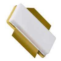
BLF573S,112 NXP Semiconductors, BLF573S,112 Datasheet - Page 8

BLF573S,112
Manufacturer Part Number
BLF573S,112
Description
TRANSISTOR RF LDMOS SOT502B
Manufacturer
NXP Semiconductors
Specifications of BLF573S,112
Transistor Type
LDMOS
Frequency
225MHz
Gain
27.2dB
Voltage - Rated
110V
Current Rating
42A
Current - Test
900mA
Voltage - Test
50V
Power - Output
300W
Package / Case
SOT502B
Application
HF/VHF
Channel Type
N
Channel Mode
Enhancement
Continuous Drain Current
42A
Drain Source Voltage (max)
110V
Output Power (max)
300W
Power Gain (typ)@vds
27.2@50VdB
Frequency (max)
225MHz
Package Type
LDMOST
Pin Count
3
Forward Transconductance (typ)
20S
Drain Source Resistance (max)
90(Typ)@6Vmohm
Input Capacitance (typ)@vds
300@50VpF
Output Capacitance (typ)@vds
103@50VpF
Reverse Capacitance (typ)
2.3@50VpF
Operating Temp Range
-65C to 225C
Drain Efficiency (typ)
70%
Mounting
Surface Mount
Mode Of Operation
CW
Number Of Elements
1
Vswr (max)
13
Screening Level
Military
Lead Free Status / RoHS Status
Lead free / RoHS Compliant
Noise Figure
-
Lead Free Status / Rohs Status
Compliant
Other names
934062175112
NXP Semiconductors
Table 9.
For production test circuit, see
Printed-Circuit Board (PCB): Rogers 5880;
thickness copper plating = 35 m.
BLF573S_2
Product data sheet
Component
B1
C1, C18
C2
C3, C4
C5, C6, C7
C8, C20
C9
C10
C11, C12, C13 multilayer ceramic chip capacitor
C14
Fig 7.
(dB)
G
p
30
28
26
24
22
0
V
f
Power gain and drain efficiency as functions of
peak envelope load power; typical values
2
DS
List of components
= 225.05 MHz.
= 50 V; I
8.1.2 2-Tone CW
100
Description
ferrite SMD bead
multilayer ceramic chip capacitor
multilayer ceramic chip capacitor
multilayer ceramic chip capacitor
multilayer ceramic chip capacitor
multilayer ceramic chip capacitor
multilayer ceramic chip capacitor
multilayer ceramic chip capacitor
multilayer ceramic chip capacitor
8.2 Test circuit
G
D
p
Dq
= 900 mA; f
200
Figure 9
300
1
= 224.95 MHz;
and
400
P
L(PEP)
001aaj615
Figure
r
= 2.2 F/m; height = 0.79 mm; Cu (top/bottom metallization);
Rev. 02 — 17 February 2009
(W)
500
10.
80
60
40
20
0
Value
100 ; 100 MHz
100 pF
39 pF
180 pF
220 pF
1 nF
4.7 F
30 pF
51 pF
43 pF
(%)
D
Fig 8.
IMD3
(dBc)
(1) I
(2) I
(3) I
(4) I
(5) I
(6) I
(7) I
(8) I
20
40
60
80
0
0
V
Third order intermodulation distortion as a
function of peak envelope load power; typical
values
[1]
[1]
[1]
[1]
[1]
[1]
[1]
[1]
Dq
Dq
Dq
Dq
Dq
Dq
Dq
Dq
DS
= 500 mA
= 700 mA
= 900 mA
= 1100 mA
= 1300 mA
= 1500 mA
= 1700 mA
= 1800 mA
Remarks
Ferroxcube BDS3/3/8.9-4S2 or equivalent
TDK C4532X7R1E475MT020U or equivalent
= 50 V; f
(8)
(7)
(6)
100
HF / VHF power LDMOS transistor
1
= 224.95 MHz; f
200
(1)
(2)
(3)
(4)
(5)
300
2
= 225.05 MHz.
BLF573S
© NXP B.V. 2009. All rights reserved.
400
P
L(PEP)
001aaj616
(W)
500
8 of 14


