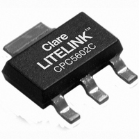
CPC5602CTR Clare, CPC5602CTR Datasheet - Page 6

CPC5602CTR
Manufacturer Part Number
CPC5602CTR
Description
MOSFET N-CH 350V 5MA SOT-223
Manufacturer
Clare
Type
Power MOSFETr
Specifications of CPC5602CTR
Fet Type
MOSFET N-Channel, Metal Oxide
Fet Feature
Depletion Mode
Rds On (max) @ Id, Vgs
14 Ohm @ 50mA, 350mV
Drain To Source Voltage (vdss)
350V
Current - Continuous Drain (id) @ 25° C
5mA
Input Capacitance (ciss) @ Vds
300pF @ 0V
Power - Max
2.5W
Mounting Type
Surface Mount
Package / Case
SOT-223 (3 leads + Tab), SC-73, TO-261
Number Of Elements
1
Polarity
N
Channel Mode
Depletion
Drain-source On-res
14Ohm
Drain-source On-volt
350V
Continuous Drain Current
5mA
Power Dissipation
2.5W
Output Power (max)
Not RequiredW
Frequency (max)
Not RequiredMHz
Noise Figure
Not RequireddB
Power Gain
Not RequireddB
Drain Efficiency
Not Required%
Operating Temp Range
-40C to 85C
Operating Temperature Classification
Industrial
Mounting
Surface Mount
Pin Count
3 +Tab
Package Type
SOT-223
Lead Free Status / RoHS Status
Lead free / RoHS Compliant
Gate Charge (qg) @ Vgs
-
Vgs(th) (max) @ Id
-
Lead Free Status / Rohs Status
Compliant
Other names
CLA298TR
CPC5602CTR
CPC5602CTR
Available stocks
Company
Part Number
Manufacturer
Quantity
Price
Company:
Part Number:
CPC5602CTR
Manufacturer:
CPCLARE
Quantity:
18 210
Company:
Part Number:
CPC5602CTR
Manufacturer:
CPCLARE
Quantity:
453
Part Number:
CPC5602CTR
Manufacturer:
CPCLARE
Quantity:
20 000
CPC2400E
6
Applications
Figure 1 is a schematic of the CPC2400E in a typical
host system application. The host system communi-
cates to the CPC2400E through a standard V.24 serial
interface. Refer to the Pinout and Definitions section for
functional descriptions of the pins. The transmit and
receive data is sent over the TXD and RXD pins. The -
DCD and -DTR pins are used for handshaking. The
audio output pin, A1 is used for monitoring the analog
data and can be amplified to drive a speaker. The -
MUTE can be used to enable or disable the speaker.
14
15
18
21
22
25
16
17
19
20
23
24
DB25F
10
11
12
13
1
2
3
4
5
6
7
8
9
TXD
RXD
SPEAKER
SYSTEM
HOST
Figure 2. Stand Alone Modem with RS232C Interface
15
14
8
9
3
7
RS232 DRIVER
LT1181A
Figure 1. CPC2400E System Environment
AUDIO AMP
+5V
17
16
-DCD
-DTR
TXD
RXD
-MUTE
11
10
13
12
18
2
4
5
6
A1
TXD
RXD
www.clare.com
CPC2410E
MODEM
+5V
VCC
GND
CPC2400E
MODEM
The ferrite beads FB1 and FB2 may be required to
reduce EMI emissions per FCC Part 15. Determining
the value for the ferrite beads depends solely on the
emissions generated by the end user product.
Figure 2 is a schematic of the CPC2400E in a stand-
alone RS232C configuration. This circuit uses the Linear
Technologies LT1181A RS232 line driver. Note that the
LT1181A line driver inverts the signals. Both figures 1
and 2 are for reference purposes only. Exact component
values should be determined by the user.
+5V
GND
VCC
TIP
RING
FB1
FB2
FB1
FB2
RING
TIP
TELEPHONE
LINE
TELEPHONE
LINE
Rev. 2


