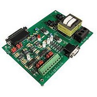
AC7 OPTO 22, AC7 Datasheet - Page 35

AC7
Manufacturer Part Number
AC7
Description
Computers, Interface Cards
Manufacturer
OPTO 22
Specifications of AC7
Peak Reflow Compatible (260 C)
No
Leaded Process Compatible
No
Features
RS232 To RS422 Converter
Interface
RS-422⁄485
Module Type
Adapter Card
Mounting Type
Protective Enclosure
Voltage, Supply
115 VAC ± 10 VAC @ 50⁄60 Hz
Lead Free Status / RoHS Status
Contains lead / RoHS non-compliant
Available stocks
Company
Part Number
Manufacturer
Quantity
Price
Part Number:
AC713
Manufacturer:
ALPHA
Quantity:
20 000
Part Number:
AC7201-50JC
Manufacturer:
AMD
Quantity:
20 000
Part Number:
AC744
Manufacturer:
SKYWORKS/思佳讯
Quantity:
20 000
Company:
Part Number:
AC76951
Manufacturer:
ALPHA
Quantity:
5 510
Part Number:
AC7C4096B012TCN
Manufacturer:
ALLIANCE
Quantity:
20 000
TROUBLESHOOTING
The AC7A/B is a simple pass-through communication converter. Troubleshooting communication problems with
the AC7A/B is simple, as long as an organized methodical approach is used. The following sequential procedure
is recommended:
a. Verify that the PWR ON LED is illuminated. If yes, go on to step “b.” If the PWR ON LED is not illuminated,
b. Verify that an RS-232 cable is connected from a computer to the 25-pin (DB25) RS-232 connector on the
c. Send data into the AC7A/B’s RS-232 port. Verify that the AC7A/B’s TX LED is flashing when data is
d. For testing purposes, temporarily disconnect any RS-422/485 wiring from the AC7A/B. Next, temporarily
e. If a software program for a computer such as Windows-Terminal or HyperTerminal is available, use it to
Note: Ensure that RS-422/485 cables are twisted-pair cables.
then use a voltmeter to verify that there is proper AC voltage across the power terminals marked “AC.”
The AC7A should have 115 VAC across the power terminals marked “AC.” The AC7B should have 220 VAC
across the power terminals marked “AC.” The AC7A or AC7B will not function correctly unless the proper
AC voltage is supplied to it.
AC7A/B. For more details on RS-232 cabling to an AC7A/B, see “Installing the AC7A/B for use with
devices other than Opto 22’s Optomux I/O” of this manual. Make sure that the RS-232 cable from the
computer to the 25-pin (DB25) RS-232 connector on the AC7A/B exactly matches the wiring diagrams
of one of the cables shown in Section 3-2 of this manual.
entering the AC7A/B’s RS-232 port. It may be necessary to slow down the RS-232 baud rate to make the
LEDs flash slower, which will make the LEDs easier to see. If the TX LED does flash, then go on to step “d.”
If the TX LED is not flashing, it may be because the RS-232 jumpers are incorrect for the type of cable being
used. See “Installing the AC7A/B for use with devices other than Opto 22’s Optomux I/O” of this manual
for detailed instructions on setting the AC7A/B RS-232 jumpers. If the TX LED is flashing, this means that
RS-232 data is being received by the AC7A/B and re-transmitted out the RS-485 (TO±) terminals.
connect the TO+ terminal to the FO+ terminal. Then temporarily connect the TO- terminal to the FO-
terminal. This will create a loop back cable on the AC7A/B’s RS-422/485 port, which will take the data
going out of the AC7A/B’s RS-422/485 transmit lines and send it back into the AC7A/B’s RS-422/485
receive lines. Now send data from a computer to the AC7A/B’s RS-232 port, and verify that both the
AC7A/B’s TX and RX LEDs are flashing when data is entering the AC7A/B’s RS-232 port. It may be
necessary to slow down the RS-232 baud rate to make the LEDs flash slower, which will make the LEDs
easier to see. If the TX LED is flashing, this means that RS-232 data is being received by the AC7A/B and
re-transmitted out the RS-422/485 transmit (TO±) terminals. But because of the RS-422/485 loop back
cable, the data is looped back from the RS-422/485 transmit (TO±) terminals into the RS-422/485 (FO ±)
receive terminals, and finally sent back to the computer through the AC7A/B’s RS-232 port.
send data out of the computer’s RS-232 port to the AC7A/B. If the RS-422/485 loop back cable is still
connected as in step “d” above, then whatever is typed on the keyboard of the computer should be
displayed on the computer’s monitor. If keys are being pressed on the computer’s keyboard, and the
AC7A/B’s TX and RX LED’s are flashing, but nothing is being displayed on the computer’s monitor, then
the most likely reasons are that (1) the terminal program or the operating system is configured for the
wrong interrupt (IRQ) line, or (2) there is an interrupt conflict between the serial port and another device in
the computer. Either or both of these conditions may need to be corrected. If data that is typed on the
keyboard of the computer is displayed on the computer’s monitor, then the AC7A/B is functioning correctly.
ADDITIONAL TECHNICAL INFORMATION
AC7A/B User’s Guide 35


