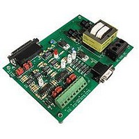
AC7 OPTO 22, AC7 Datasheet - Page 34

AC7
Manufacturer Part Number
AC7
Description
Computers, Interface Cards
Manufacturer
OPTO 22
Specifications of AC7
Peak Reflow Compatible (260 C)
No
Leaded Process Compatible
No
Features
RS232 To RS422 Converter
Interface
RS-422⁄485
Module Type
Adapter Card
Mounting Type
Protective Enclosure
Voltage, Supply
115 VAC ± 10 VAC @ 50⁄60 Hz
Lead Free Status / RoHS Status
Contains lead / RoHS non-compliant
Available stocks
Company
Part Number
Manufacturer
Quantity
Price
Part Number:
AC713
Manufacturer:
ALPHA
Quantity:
20 000
Part Number:
AC7201-50JC
Manufacturer:
AMD
Quantity:
20 000
Part Number:
AC744
Manufacturer:
SKYWORKS/思佳讯
Quantity:
20 000
Company:
Part Number:
AC76951
Manufacturer:
ALPHA
Quantity:
5 510
Part Number:
AC7C4096B012TCN
Manufacturer:
ALLIANCE
Quantity:
20 000
ADDITIONAL TECHNICAL INFORMATION
34 AC7A/B User’s Guide
If none of the RS-485 transmitters need to talk, they may all be disabled. In this case, the communication line is
floating because it is not being driven to some definite HIGH or LOW state. To resolve this, biasing resistors are
needed to put the transmission line in a known, predefined state. This prevents electrical noise from causing the
communication line to float HIGH or LOW when the RS-485 line is idle. Otherwise, an RS-485 receiver may
incorrectly interpret the noise on the communication line as data. Since the transmission line is actually made up of
two wires, one resistor for each wire is needed. However, only one pair of biasing resistors may be placed on an
RS-485 network. Jumpers are provided on the AC7A/B to connect the biasing resistors to the RS-485 communication
lines. If biasing is already accomplished at some other point on the RS-485 line, then the biasing resistor jumpers
should be removed on the AC7A/B.
In summary, an RS-485 communication line must be terminated at both ends by having a terminating resistor placed
across the pair of wires that make up a single data line. In addition, the RS-485 data line must be biased at one
location only.
Communication Jumpers
Group B and C jumpers configure the RS-422/485 lines. These determine the biasing and termination of the wires
and they also control the enabling of the RS-422/485 transmitter (TO) and the RS-422/485 receiver (FO).
As shown in the diagram above, B1, B3, C1, C3, B5, B6, C5, and C6 connect the RS-422/485 lines to biasing resistors.
B2, C2, B4, and C4 insert terminating resistors across the pairs of wires used in each RS-422/485 line. B7, C7,
and B8 control whether the TO driver and FO receiver can be enabled/disabled by RTS or CTS. For more information
concerning RS-422/485 and the need for biasing and terminating, see Biasing and Terminating RS-422/485 on
page 29.
Figure 4-6: Communication Jumpers


